标题:
ATMEGA16单片机usart通信(主从多机通信)proteus仿真与源码
[打印本页]
作者:
8696
时间:
2018-1-14 15:18
标题:
ATMEGA16单片机usart通信(主从多机通信)proteus仿真与源码
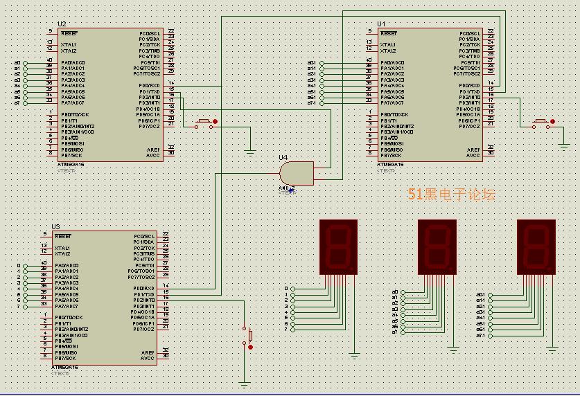
ATMEGA16 usart通信仿真原理图如下(proteus仿真工程文件可到本帖附件中下载)
0.jpg
(140.5 KB, 下载次数: 82)
下载附件
2018-1-14 17:12 上传
一共3个单片机,一个主机 2个从机实现多机通信效果
0.png
(6.19 KB, 下载次数: 88)
下载附件
2018-1-14 17:13 上传
全部资料51hei下载地址:
usart通信.zip
(188.5 KB, 下载次数: 81)
2018-1-14 15:18 上传
点击文件名下载附件
下载积分: 黑币 -5
部分单片机源程序如下:
/*****************************************************
This program was produced by the
CodeWizardAVR V2.05.1b Evaluation
Automatic Program Generator
?Copyright 1998-2011 Pavel Haiduc, HP InfoTech s.r.l.
Project :
Version :
Date : 2017/12/21
Author : Freeware, for evaluation and non-commercial use only
Company :
Comments:
Chip type : ATmega16
Program type : Application
AVR Core Clock frequency: 4.000000 MHz
Memory model : Small
External RAM size : 0
Data Stack size : 256
*****************************************************/
#include <mega16.h>
flash unsigned char led_7[10]={0x3f,0x06,0x5b,0x4f,0x66,0x6d,0x7d,0x07,0x7f,0x6f};
unsigned char point=0;
// External Interrupt 0 service routine
interrupt [USART_RXC] void usart_rx_isr(void) //接收中断服务
{
unsigned char status,resh,resl;
status=UCSRA;
resh=UCSRB;
resl=UDR;
if((status&(1<<4|(1<<3)|1<<2)) ==0)
{
resh=(resh>>1)&0x01;
if (resh==0)
PORTA=led_7[resl];
else
PORTA=0x00;
}
#asm("sei")
}
interrupt [EXT_INT0] void ext_int0_isr(void)
{
// Place your code here
while(!(UCSRA&(1<<5)));
UDR=point;
#asm("sei")
}
// Standard Input/Output functions
#include <stdio.h>
// Declare your global variables here
void main(void)
{
// Declare your local variables here
// Input/Output Ports initialization
// Port A initialization
// Func7=Out Func6=Out Func5=Out Func4=Out Func3=Out Func2=Out Func1=Out Func0=Out
// State7=0 State6=0 State5=0 State4=0 State3=0 State2=0 State1=0 State0=0
PORTA=0x00;
DDRA=0xFF;
// Port B initialization
// Func7=In Func6=In Func5=In Func4=In Func3=In Func2=In Func1=In Func0=In
// State7=T State6=T State5=T State4=T State3=T State2=T State1=T State0=T
PORTB=0x00;
DDRB=0x00;
// Port C initialization
// Func7=In Func6=In Func5=In Func4=In Func3=In Func2=In Func1=In Func0=In
// State7=T State6=T State5=T State4=T State3=T State2=T State1=T State0=T
PORTC=0x00;
DDRC=0x00;
// Port D initialization
// Func7=In Func6=In Func5=In Func4=In Func3=In Func2=In Func1=In Func0=In
// State7=T State6=T State5=T State4=T State3=T State2=T State1=T State0=T
PORTD=0x03;
DDRD=0x02;
// Timer/Counter 0 initialization
// Clock source: System Clock
// Clock value: Timer 0 Stopped
// Mode: Normal top=0xFF
// OC0 output: Disconnected
TCCR0=0x00;
TCNT0=0x00;
OCR0=0x00;
// Timer/Counter 1 initialization
// Clock source: System Clock
// Clock value: Timer1 Stopped
// Mode: Normal top=0xFFFF
// OC1A output: Discon.
// OC1B output: Discon.
// Noise Canceler: Off
// Input Capture on Falling Edge
// Timer1 Overflow Interrupt: Off
// Input Capture Interrupt: Off
// Compare A Match Interrupt: Off
// Compare B Match Interrupt: Off
TCCR1A=0x00;
TCCR1B=0x00;
TCNT1H=0x00;
TCNT1L=0x00;
ICR1H=0x00;
ICR1L=0x00;
OCR1AH=0x00;
OCR1AL=0x00;
OCR1BH=0x00;
OCR1BL=0x00;
// Timer/Counter 2 initialization
// Clock source: System Clock
// Clock value: Timer2 Stopped
// Mode: Normal top=0xFF
// OC2 output: Disconnected
ASSR=0x00;
TCCR2=0x00;
TCNT2=0x00;
OCR2=0x00;
// External Interrupt(s) initialization
// INT0: On
// INT0 Mode: Falling Edge
// INT1: Off
// INT2: Off
GICR|=0x40;
MCUCR=0x02;
MCUCSR=0x00;
GIFR=0x40;
// Timer(s)/Counter(s) Interrupt(s) initialization
TIMSK=0x00;
// USART initialization
// Communication Parameters: 8 Data, 1 Stop, No Parity
// USART Receiver: On
// USART Transmitter: On
// USART Mode: Asynchronous
// USART Baud Rate: 9600
UCSRA=0x00;
UCSRB=0x9d;
UCSRC=0x86;
UBRRH=0x00;
UBRRL=0x19;
// Analog Comparator initialization
// Analog Comparator: Off
// Analog Comparator Input Capture by Timer/Counter 1: Off
ACSR=0x80;
SFIOR=0x00;
……………………
…………限于本文篇幅 余下代码请从51黑下载附件…………
复制代码
所有资料51hei提供下载:
欢迎光临 (http://www.51hei.com/bbs/)
Powered by Discuz! X3.1
 usart通信.zip
(188.5 KB, 下载次数: 81)
usart通信.zip
(188.5 KB, 下载次数: 81)