cxxx180 发表于 2025-6-28 01:02 是的。你说的是对的,按着你的建议,我改好了,问题解决了。 谢谢。 |
| 不知你是怎样的驱动电路,理论上加分压电阻可以正常显示 |
| 问题的原因找到了,主要问题点是设计转换电路上(位选控制驱动信号相位,没有转换,直接驱动)出来状况,谢谢诸位提出的建议。 |
| 建议楼主去除D1,将Q15的E极接GND,单片机的驱动口配置为推挽输出模式后再试试看。 |
|
1,可以测试一下12V电压是否稳定。 2,5V电源的地是否与12V电源的地可靠连接。 |
fengyun6198 发表于 2025-6-27 15:29 第一张图公共引脚也要和第二张一样处理,极性相反。 |
| 🔍 Possible Causes of the Flickering: 1. Incorrect Level Shifting / Driving Logic If you're still using 5V logic signals (e.g., from a microcontroller or TTL), they may not be able to properly switch the 12V supply through the driver circuit, especially if the driver requires a certain input voltage to turn on fully (like a transistor base or MOSFET gate). 2. Insufficient Current or Pull-down Resistance When switching higher voltages, you may need pull-down resistors or MOSFET drivers to cleanly switch the segment lines. Otherwise, the segments can float or partially turn on, causing visible flickering. 3. Driver Circuit Configuration You mentioned adding a driver circuit—if it’s a transistor or MOSFET array, make sure: The gate/base is driven properly (use resistor if needed). You are using NPN or N-MOS for low-side switching, or PNP/P-MOS for high-side switching, depending on your design. Proper current-limiting resistors are used for each segment. 4. Timing or Refresh Rate If you are using multiplexing (scanning digits one at a time), and the refresh rate is too low, it can cause flickering. Make sure the scanning happens fast enough (>60 Hz per digit) for a stable visual effect. 💡 Suggestions: Double-check your driver circuit—post a diagram if you can. Verify voltage levels going into the segment pins. Try measuring with a multimeter or oscilloscope to see if the segment pins are toggling cleanly between 0V and 12V. If using a microcontroller, consider adding a level shifter IC (like 74HCT series) between the MCU and the high-voltage side. |
cxxx180 发表于 2025-6-26 16:57 请看图,图中小写(a)网络是原来信号输出驱动数码管a段信号源,现用来作12V数码管的驱动信号;大写(A)网络是12V电源 转换输出给12V数码管a段提供电源,你摞一摞,输出信号与驱动信号是同相。 |
fengyun6198 发表于 2025-6-27 07:56 那么段码的驱动电路在哪儿? |
zhang32568 发表于 2025-6-26 22:31 原来的数码管型号:5V供电的共阴管。现在的型号是12V供电的共阴管,提供的电路图就是12V电源电路,应该很详细呀? |
|
你的描述让人云里雾里 数码管分电压码? 你的意思是不是原数码管供电是5V ,现在改用12V给原数码管供电不能正常显示。(数码管还是原来的数码管,只是供电电压由5V变成12V |
飞云居士 发表于 2025-6-26 14:06 12V 电源回路中串接了一个限流电阻220R,电流不会过大。 |
cyi8 发表于 2025-6-26 14:39 原来用的是5V 共阴数码管,现改成12V的共阴数码管。不知道是什么原因引起的,12V的数码管显示不正常 |
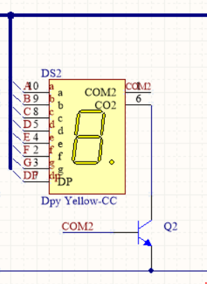
Q2不对劲啊,你改电压,要用两个三极管倒相两次才行,不然共阴数码管改12V得换共阳数码管 |
| 遮遮掩掩的最重要的数码管是谁驱动的,把他放出来,他的供电如何,放两个三极管有啥好看的 |
|
你这个描述搞得我有点懵,到底是 原来用5V电源驱动的板,直接改成了12V电源驱动,数码管没有更换 还是原来5V电源的板,现在用5V电源驱动,但换了一个需要12V驱动的数码管. 还是原来5V电源的板,现在用12V电源驱动,数码管也换成了12V驱动的数码管. 没有说清楚,不知道怎么回答.只能给几个参考意见 有可能是更改供电电压后,外围电路降压给MCU和芯片用的电压高了,导致芯片不稳定. 也有可能是供电电压低了,导致数码管闪铄. 如果是供电电压高了,电路有保护,也会有影响. 还有看你改的电路,有没有考虑过三极管的参数,导通与关断的条件,是不是三极管导通后到了放大区,导致电流不稳定. |
| 直接改用12V,原电路器件参数按5V,用12V加上,其电流过大,引起电源保护断电,再恢复再断电,所以闪烁。 |
 收藏
收藏 顶
顶 踩
踩

