|
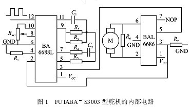
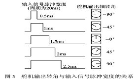
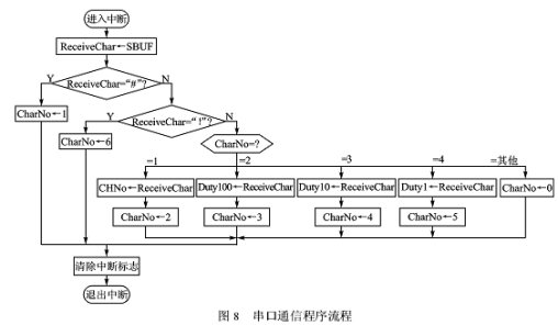
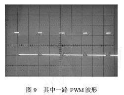
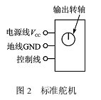
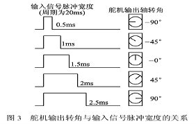
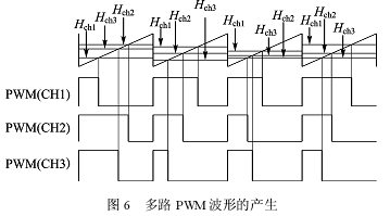
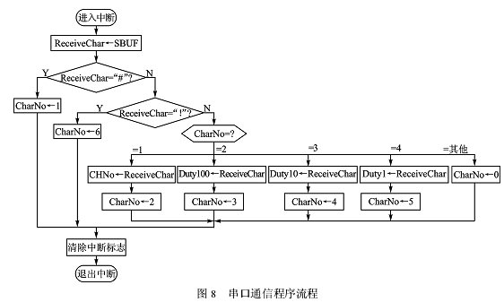
外文翻译2 原文: Based on The AT89C2051 Servo Controller Design Author:Huabo Wu Cunlai Qian Abstract Steering robot, electrical system, and is the important actuators hog. The controller for steering gear to provide the necessary energy and control signals. This paper proposes a kind of external interruption to count on the basis of PWM waves method. This method is simple and convenient, low cost, can achieve more independent PWM output advantages of road. Keywords: AT89C2051 steering PWM controller external interruption Introduction: Steering gear is a kind of position servo drive. It receives some control signal output and certain Angle,applicable to those who need Angle and can keep the control system.In microelectromechanical system and rc, it is one of the basic output actuators. 1.The working principle of steering gear In Japan S3003 FUTABA type steering gear, for example, the figure 1 is the FUTABA - S3003 type steering internal circuitry. The working principle of PWM signal is: by receiving signal demodulating circuit BA6688L channel into 12 feet were demodulated, get a dc bias voltage. The dc bias voltage and comparison, the voltage potentiometer voltage difference of three feet by BA6688 output. The output into motor drive IC BAL6686 to drive motor rotation. When the motor speed through a certain cascade reduction gear drive Rw1 potentiometer, until the voltage difference for 0, the motor stopped rotating. Servo control signal is using PWM signal, SHCH changes of steering gear. 2.the steering gear control method Standard of steering gear with three wires, respectively is: power, ground, line, as shown in figure 2. Power and ground for the internal control circuit of dc motor and the energy needed, voltage usually between 4 ~ 6 V, one As take 5 V. Note that the power supply for steering gear should provide enough power to. Line of input is a pulse width can be adjusted periodically pulse signal,the square of the pulse signal for 20 to 50 ms (i.e. frequency speed). When the pulse width of the pulse change, steering shaft Angle of view, change with the changes of the pulse width is proportional to the change. A type of steering Angle and the input signal output shaft of the relationship between pulse width is available to figure 3. 3. the controller design (1)the controller hardware circuit design From the Angle of steering gear control method can see, steering gear control signal is an adjustable width of the pulse signal( PWM ). The pulse signal by the FPGA, analog circuits or microcontroller. Adopted FPGA cost is higher, with analog circuit is complicated circuit to realize multiple output, are generally made of steering gear adopts single-chip microcomputer controller. Now do the one-chip computer controller, can use more scheme of microcontroller timer interrupt realize PWM. The plan will be 20 ms periodic signal is divided into two regularly interrupted: a regular realize high-level timing Th, A regular realize low level timing Tl. Th, the time value of Tl with pulse width of transformation and change but Th + Tl = 20 ms. The advantage of this method is completely by MCU, PWM signal inside the timer interruption to realize, need not add peripheral hardware faults is a cycle of PWM signal to interrupt, two for calculating the interruption twice as a trouble, In order to satisfy the cycle, 20 ms chip to reduce the frequency of crystals, Not realizing multi-way output. Can also adopts singlechip + 8253 counter scheme. The scheme of microcomputer produce counting pulse (or an external circuit counting pulse) to count by MCU, 8253 is compared to the count 8253 output pulse-width change the advantages of the plan is to achieve more ways of output, software design is simple, Defect is to add 1 piece 8253 counter, increase the cost of hardware. Based on the combination of the two microcontroller steering gear control scheme is proposed, based on a new design scheme, as shown in figure 4. 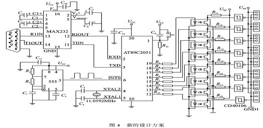 The scheme of the controller to AT89C2051 singlechip, consisting of a regular 555 oscillator, SCM based on the pulse signal generated 555 oscillator to generate PWM signal count. This control The SCM can produce eight PWM channels signal, the P1.0 ~ P1.7 by AT89C2051 (12-19 pin) ports output. The eight PWM signal output by light-coupler to lower level isolation circuit. Because the signal transmitted through light-coupler process, so the signals from light-coupler to inverter reverse phase. Pulse signal transmission through light-coupler, frontier and the distortion, so will happen CD40106 schmidt inverter adopts inverter of optical coupling transmission signals, produce plastic PWM signal. Standard torque-current In the process of experiment, steering gear in the operation process of absorbing from power steering gear and current, if share a microcomputer controller, servo will to power of chip. Therefore, the microcomputer controller and power supply, two by two, not to isolate light-coupler through, and the power supply for steering the output power of switch power. The steering gear controller chip occupy 1 SCI serial port. Serial transmission come to accept a PC control commands,to adjust the output signal of each channel pulse width. MAX232 for level of PC converter, will convert TTL multilevel RS232 level. (2)multi-way PWM signal principle In analog circuits, PWM pulse signal can be through with the sawtooth wave signal dc level compared to get. In the SCM,sawtooth wave can be based on an integer 1 operation to realize, as shown in figure 5. Assuming microcontroller program Set a variable in the value of a range of ~. SawVal, 0 N 555 oscillating circuit of external clock signal input to count the feet. INT0 AT89C2051 Whenever in the external counting down the clock pulse, the microcontroller generate external interruption along,INT0 external interruption of an interrupt service routine. Each time to generate external interruption, SawVal execution time plus 1 operation, if SawVal has reached the maximum N, to SawVal qing 0.SawVal value change rule of the equivalent of sawtooth wave, as shown in figure 5. If the microcontroller program in the whole set of DutyVal variables, the range of 0 ~ N. Whenever SawVal in qing dynasty, from the upper DutyVal 0In order to send machine control input pulse width coefficient values, such as H ( 0 acuities H acuities N ). If DutyVal SawVal p, corresponding to the high power lost ports; If DutyVal < SawVal, the corresponding ports output low level. Can see from figure 5, if change DutyVal value, the corresponding ports output pulse width changes, but the output pulse frequency, this is for PWM waves. Set the clock cycle count for external TINT0, sawtooth wave period ( PWM pulse cycle ) for TPWM PWM pulse width,SHCH as D, figure 5 can draw as follows: By type ( 3 ), TPWM cycle of PWM waves, only once selected counting maximum N, can determine the external clock pulse frequency required cycle ( Frequency ). External clock cycle TINT0 apparently PWM pulse width transform interval, namely, the minimum regulation accuracy. By type(4), N, is occupied the smaller percentage of PWM cycle, higher accuracy. For example, if the eight using 8-bit integer variables, the maximum N = 2-1 = 255, accuracy of 1/16 ( 255 + 1 ) = 1/256, If using 16-bit an integer value, N = 2-1 = 65 535, precision for 1/65 536. The counter variable SawVal using 8-bit integer variables, N = 255. In general, the accuracy of the application is enough. Just as TPWM requirements, steering gear = 20 ms, can calculate external clock cycle for: Therefore, when the oscillating circuit design 555, the output pulse frequency should be: When more than one variable and SawVal comparison, comparing to multiple outputs, formed port multi-channel PWM waves. Variables can be independent of value, so each change of PWM SHCH can also independent regulation, each other. Multiple PWM waves generated as shown in figure 6. Graph 3 road of PWM waves, for example. 4. the controller of software design Steering gear control core controller for a single chip microcomputer AT89C2051. This program written by C51 and way of working for QianHouTai way to work. Microcontroller program including system initialization procedures, serial communication program, PC and ordered a PWM pulse-width generating procedures and multi-channel PWM output process. Serial communication program and multiple output program using PWM interruption. Serial communication format for baud rate and 600 BPS, 8 bits of data bits, and stop bits, calibration, ASCII characters. Serial communication program for receiving PC to send over control commands. Control command by custom text content, in which the protocol agreement for the ASCII characters. Communication protocol format, as shown in figure 7. 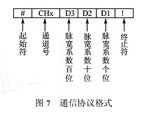 For example, to control the PWM channels 1 pulse width, pulse width coefficient for 25, communication protocol for "#" content "1", "2", "0", "5"!" The six characters. This passage 1 PWM SHCH as 25/256 = 0.098. A channel number corresponds to a PWM pulse output port. This design for 8 channels, the number is 1-8, corresponding to the P1.0 ~ P1.7 chip. Starting and termination of the role play frame synchronization. Serial communication processes as shown in figure 8. Figure 8, CHNo deposit is PWM channels, Duty100, Duty10 ASCII code, and stored Duty1 respectively the pulse width of the coefficient is 100 digits, ten digits and single-digit ASCII ( note, if high digits 0, then it should be "0" the character, not omit. 25,complete characters should be "0" "2" and "five" ). CharNo for signal, used to receive the characters and serial interrupt and superordination machine serial order process between the synchronization. 5 .the controller experiment Figure 9 for steering gear control panel output of PWM waves along with servo load ( . ). Can see from figure 9 PWM controller outputs, steering stability, clean, wave meet the design requirement. 6 ."theory In this paper the steering gear controller design method, as the core, with a single chip microcomputer AT89C2051 by external oscillating circuit provides PWM pulse timing benchmark, control and steering gear drive by two power supply, both electrical isolation. This kind of design scheme is: 1 PWM waves from external oscillating circuit chip, and provide timing benchmark internal oscillator frequency, do not affect serial communication, timer and other parameters of the configuration. 2 accuracy of PWM waves can be arbitrary. 3 this design can be applied to any number of PWM output, as long as SCM can provide enough output port, for example, can change AT89C2051 AT89S51 provide at least 24 PWM output ( P2 ) P0, P1. 4 by SCI serial input control parameters, wide adaptability, PC can be PCS, SCM or PLC. This method possesses 5, any microcontroller as long as can provide SCI interrupt and external interruption, this method can be applied. References [1] facts technology. The typical examples of navigation module design chip. Beijing: people's press, 2004. [2] microcontroller PWM signal for steering gear control. WWW. Vip998.com/right/MCU McUyj / 200603/237. / HTML. 译文: 基于AT89C2051的多路舵机控制器设计 作者:吴华波 钱春来 摘要 舵机是机器人、机电系统和航模的重要执行机构。舵机控制器为舵机提供必要的能源和控制信号。本文提出一种以外部中断计数为基础的 PWM 波形实现方法。该方法具有简单方便,成本低,可实现多路独立 PWM 输出的优点。 关键词: AT89C2051;舵机;控制器;外部中断;PWM 引言: 舵机是一种位置伺服的驱动器。它接收一定的控制信号,输出一定的角度,适用于那些需要角度不断变化并可以保持的控制系统。在微机电系统和航模中,它是一个基本的输出执行机构。 1 舵机的工作原理 以日本 FUTABA S3003型舵机为例,图1是 FUTABA-S3003 型舵机的内部电路。 舵机的工作原理是:PWM 信号由接收通道进入信号解调电路BA6688L 的12 脚进行解调,获得一个直流偏置电压。该直流偏置电压与电位器的电压比较,获得电压差由BA6688 的 3 脚输出。该输出送入电机驱动集成电路BAL6686,以驱动电机正反转。当电机转速一定时, 通过级联减速齿轮带动电位器 Rw1旋转,直到电压差为0,电机停止转动。舵机的控制信号是 PWM 信号,利用占空比的变化改变舵机的位置。 2 舵机的控制方法 标准的舵机有 3 条导线,分别是:电源线、地线、控制线,如图2 所示。电源线和地线用于提供舵机内部的直流电机和控制线路所需的能源,电压通常介于 4~6 V ,一般取5 V。注意,给舵机供电的电源应能提供足够的功率。控制线的输入是一个宽度可调的周期性方波脉冲信号,方波脉冲信号的周期为 20 ms(即频率为50 Hz)。当方波的脉冲宽度改变时,舵机转轴的角度发生改变,角度变化与脉冲宽度的变化成正比。某型舵机的输出轴转角与输入信号的脉冲宽度之间的关系可用图3来表示。 3 舵机控制器的设计 (1) 舵机控制器硬件电路设计 从上述舵机转角的控制方法可看出,舵机的控制信号实质是一个可调宽度的方波信号(PWM) 。该方波信号可由 FPGA、模拟电路或单片机来产生。采用 FPGA 成本较高,用模拟电路来实现则电路较复杂,不适合作多路输出一般采用单片机作舵机的控制器。目前采用单片机做舵机控制器的方案比较多,可以利用单片机的定时器中断实现 PWM。该方案将20 ms 的周期信号分为两次定时中断来完成: 一次定时实现高电平定时 Th ;一次定时实现低电平定时 Tl 。Th 、Tl的时间值随脉冲宽度的变换而变化但 Th + Tl =20 ms。该方法的优点是,PWM 信号完全由单片机内部定时器的中断来实现,不需要添加外围硬件缺点是一个周期中的 PWM 信号要分两次中断来完成,两次中断的定时值计算较麻烦;为了满足20ms 的周期,单片机晶振的频率要降低;不能实现多路输出。也可以采用单片机+8253 计数器的实现方案。该方案由单片机产生计数脉冲(或外部电路产生计数脉冲)提供给8253 进行计数,由单片机给出8253 的计数比较值来改变输出脉宽该方案的优点是可以实现多路输出,软件设计较简单;缺点是要添加 1 片 8253 计数器,增加了硬件成本。本文在综合上述两个单片机舵机控制方案基础上,提出了一个新的设计方案,如图4 所示。 该方案的舵机控制器以 AT89C2051 单片机为核心,555 构成的振荡器作为定时基准,单片机通过对555 振荡器产生的脉冲信号进行计数来产生 PWM 信号。该控制 器中单片机可以产生 8 个通道的 PWM 信号,分别由AT89C2051 的 P1.0~P1.7(12~19 引脚) 端口输出。输出的8 路 PWM 信号通过光耦隔离传送到下一级电路中。因为信号通过光耦传送过程中进行了反相,因此从光耦出来的信号必须再经过反相器进行反相。方波信号经过光耦传输后,前沿和后沿会发生畸变,因此反相器采用CD40106 施密特反相器对光耦传输过来的信号进行整形,产生标准的 PWM 方波信号。笔者在实验过程中发现,舵机在运行过程中要从电源吸纳较大的电流,若舵机与单片机控制器共用一个电源,则舵机会对单片机产生较大的干扰。因此,舵机与单片机控制器采用两个电源供电,两者不共地,通过光耦来隔离,并且给舵机供电的电源最好采用输出功率较大的开关电源。该舵机控制器占用单片机的1个SCI串口。串口用于接收上位机传送过来的控制命令,以调节每一个通道输出信号的脉冲宽度。MAX232 为电平转换器,将上位机的 RS232 电平转换成 TTL 电平。 (2) 实现多路 PWM信号的原理 在模拟电路中,PWM 脉冲信号可以通过直流电平与锯齿波信号比较来得到。在单片机中,锯齿波可以通过对整型变量加1 操作来实现,如图5 所示。假定单片机程序 中设置一整型变量 其值变化范围为 ~ 。SawVal , 0 N 555振荡电路产生的外部计数时钟信号输入到 AT89C2051 的INT0脚。每当在外部计数时钟脉冲的下降沿,单片机产生外部中断,执行外部中断INT0的中断服务程序。每产生一次外部中断,对 SawVal 执行一次加1 操作,若 SawVal 已达到最大值 N ,则对 SawVal 清 0。SawVal 值的变化规律相当于锯齿波,如图5 所示。若在单片机程序中设置另一整型变量 DutyVal ,其值的变化范围为 0~N。每当在SawVal 清 0 时,DutyVal 从上位机发送的控制命令中读入脉冲宽度系数值,例如为 H(0 ≤H ≤N)。若DutyVal ≥SawVal,则对应端口输出高电平; 若 DutyVal <SawVal ,则对应端口输出低电平。从图5 中可看出,若改变 DutyVal的值,则对应端口输出脉冲的宽度发生变化,但输出脉冲的频率不变,此即为 PWM波形。 设外部计数时钟周期为 TINT0 ,锯齿波周期(PWM 脉冲周期)为TPWM ,PWM 脉冲宽度占空比为 D,由图5 可得出如下关系: 由式(3)可知,PWM 波形的周期 TPWM一旦确定下来,只须选定计数最大值 N,就可以确定外部时钟脉冲所需周期(频率)。外部时钟脉冲周期 TINT0 显然是 PWM 脉冲宽度变换的最小步距,即调节精度。由式(4)可知,N 越大,步距所占 PWM 周期的百分比越小,精度越高。例如,若8采用8 位整型变量,最大值 N = 2 - 1 =255,则精度为1/16(255 +1) =1/256;若采用16 位整型变量,最大值 N = 2- 1 =65 535,则精度为1/65 536。文中计数变量 SawVal采用8 位整型变量,因此 N =255。对于一般应用,其精度已足够。就舵机而言,要求 TPWM = 20 ms,则可算得外部时钟周期为: 因此,设计555 振荡电路时,其输出脉冲的频率应为: 当有多个变量与 SawVal 比较,将比较结果输出到多个端口时,就形成了多路 PWM 波形。各个变量的值可以独立变化,因此各路 PWM 波形的占空比也可以独立调节,互不相干。多路 PWM 波形的产生如图6 所示。图中以3 路 PWM 波形为例。 4 舵机控制器软件的设计 舵机控制器的控制核心为单片机 AT89C2051。文中,程序用 C51 编写,工作方式为前后台工作方式。单片机程序包括系统初始化程序、串口通信程序、上位机命令解释与 PWM 脉宽生成程序和多路 PWM 波形输出程序。串行通信程序和多路 PWM 波形输出程序采用中断方式。串口通信格式为波特率 9 600 bps、8 位数据位、1 位停止位、无校验、ASCII 码字符通信。串口通信程序用于接收上位机发送过来的控制命令。控制命令采用自定义文本协议,即协议内容全部为ASCII码字符。通信协议格式如图7 所示。 例如,要控制通道1 的 PWM 脉宽,脉宽系数为25,则通信协议内容为“#”“1”“0”“2”“5”“!”这6 个字符。这时通道1 的 PWM 占空比为25/256 =0.098。一个通道号对应一个 PWM 脉冲输出端口。本设计为8 个通道,号码为1~8,对应单片机的 P1.0~P1.7。起始符和终止符起到帧同步的作用。串口通信程序流程如图8 所示。 图8 中,CHNo 存放的是 PWM 通道号 ASCII 码,Duty100、Duty10、Duty1 分别存放的是脉宽系数的百位数、十位数和个位数的 ASCII 码(注意,若高位数为 0,则该位的字符应为“0”,不能省略。如25,完整字符应为“0”“2”“5”)。CharNo 为信号量,用于对串口接收的字符顺序以及串口中断与上位机命令解释程序之间进行同步。 5 舵机控制器实验 图9 为舵机控制板输出的其中一路 PWM 波形(带舵机负载)。从图9 中可看出,舵机控制器输出的 PWM 波形稳定、干净,符合设计要求。 6 结 论 本文提出的多路舵机控制器设计方法,以单片机AT89C2051 为核心,由外部振荡电路提供 PWM 脉冲的定时基准,控制部分与舵机驱动部分由两个电源供电,两者电气隔离。这种设计方案的优点是: ①PWM 波形由外部振荡电路提供定时基准,与单片机内部振荡器的频率无关,不影响串口通信、定时器等参数的配置。 ②PWM波形的调整精度可任意确定。 ③本设计思路可应用于任意多路的 PWM 输出,只要单片机能提供足够多的输出端口,例如将AT89C2051换成AT89S51,就可以提供至少24 路的 PWM 输出 (P0、P1、P2)。 ④控制参数由 SCI串口输入,适应面广,上位机可以是 PC机、单片机或是 PLC。 | 


 QQ好友和群
 QQ空间
QQ空间 腾讯微博
腾讯微博 腾讯朋友
腾讯朋友 收藏
收藏 淘帖
淘帖 顶
顶 踩
踩

