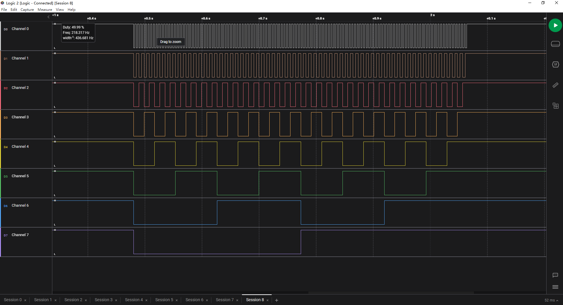
简介:配合Python上位机独立控制51单片机的4个GPIO端口的输入输出,在9600波特率下通过上位机控制MCU翻转IO速率达到218Hz,可适用于低速情况下的自动化测试场景。本项目仅供学习娱乐,可能存在未知问题和疏漏,不建议用于真实场景,对此不负任何责任。
关于通信协议:
默认波特率为9600,使用偶校验
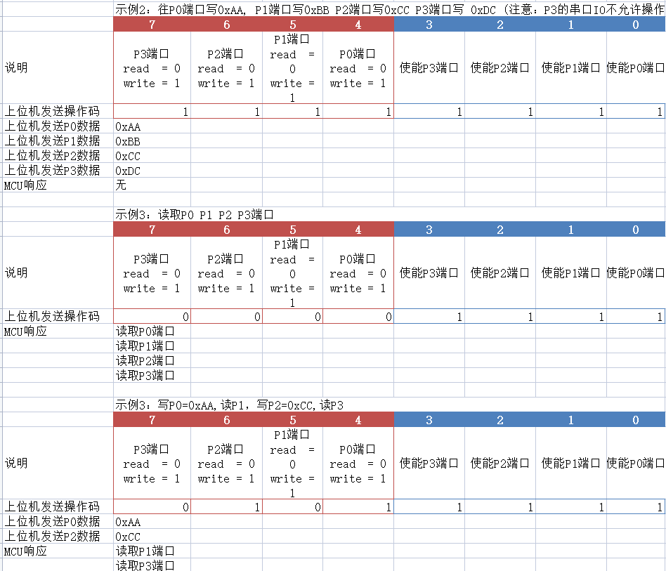
| 数据位 | 7 | 6 | 5 | 4 | 3 | 2 | 1 | 0 | | 说明 | P3端口
read = 0
write = 1 | P2端口
read = 0
write = 1 | P1端口
read = 0
write = 1 | P0端口
read = 0
write = 1 | 使能P3端口 | 使能P2端口 | 使能P1端口 | 使能P0端口 |
示例:

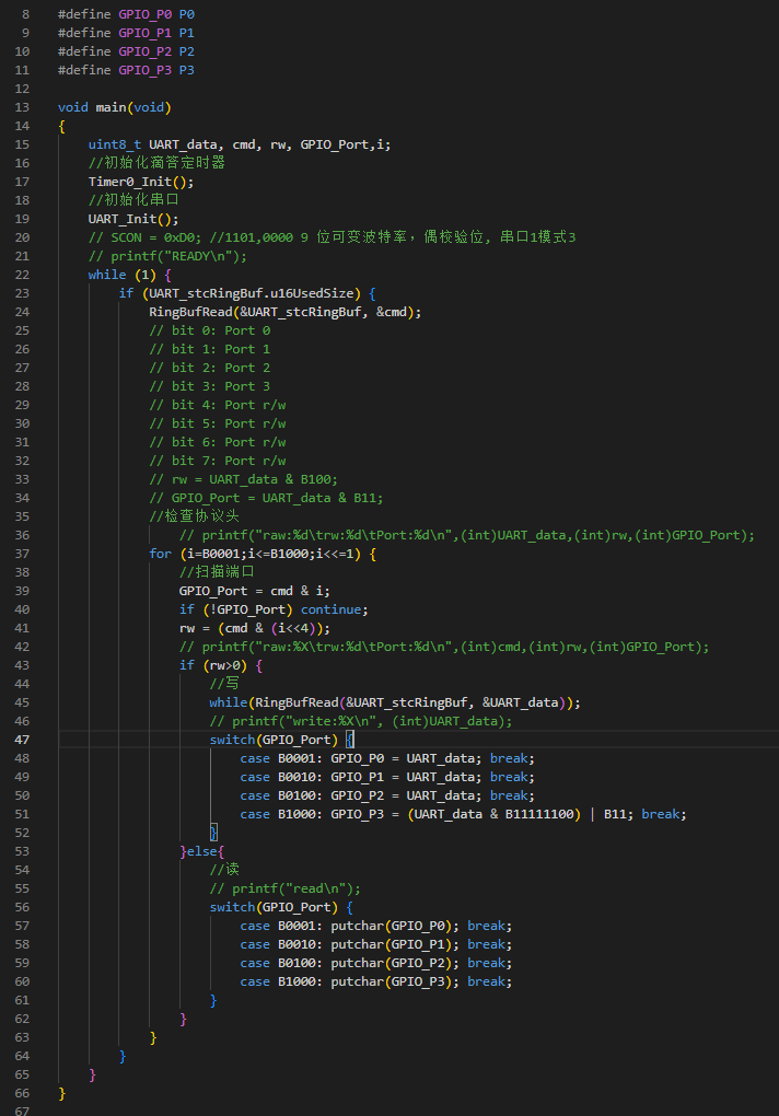
MCU代码:
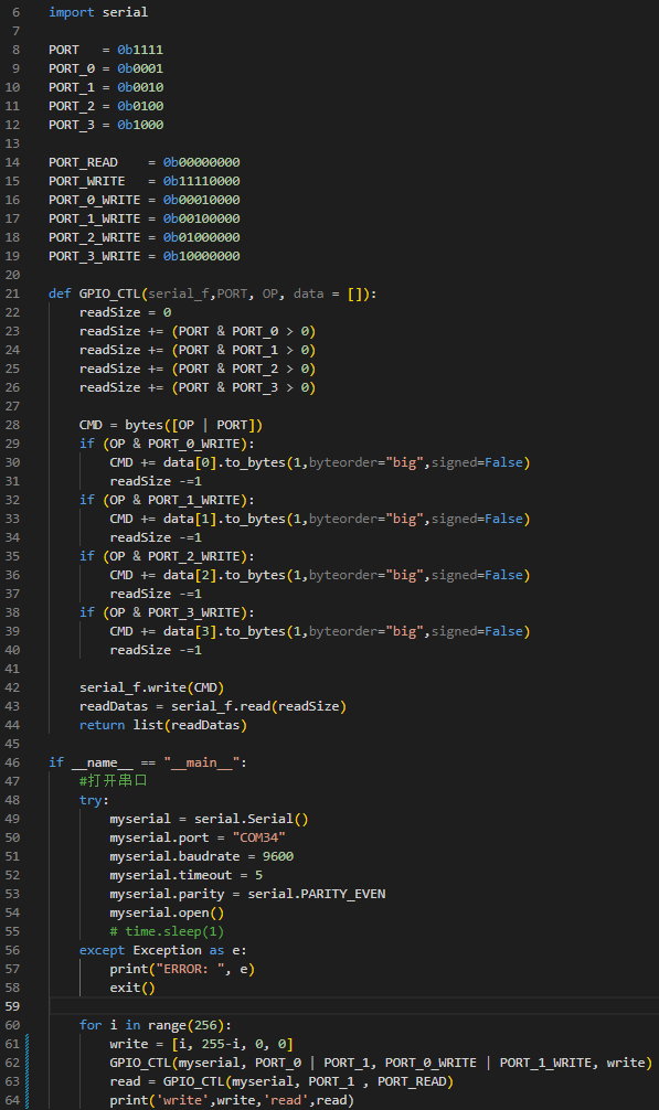
Python上位机代码:
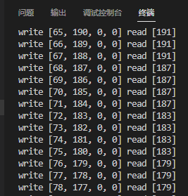
- # TEST = 0x00
- # ERASE_EXTERNAL_FLASH_SECTOR = 0x06
- # WRITE_EXTERNAL_FLASH_SECTOR = 0x07
- # READ_SECTOR = 0x08
- # RESET = 0x04
- import serial
- PORT = 0b1111
- PORT_0 = 0b0001
- PORT_1 = 0b0010
- PORT_2 = 0b0100
- PORT_3 = 0b1000
- PORT_READ = 0b00000000
- PORT_WRITE = 0b11110000
- PORT_0_WRITE = 0b00010000
- PORT_1_WRITE = 0b00100000
- PORT_2_WRITE = 0b01000000
- PORT_3_WRITE = 0b10000000
- def GPIO_CTL(serial_f,PORT, OP, data = []):
- readSize = 0
- readSize += (PORT & PORT_0 > 0)
- readSize += (PORT & PORT_1 > 0)
- readSize += (PORT & PORT_2 > 0)
- readSize += (PORT & PORT_3 > 0)
- CMD = bytes([OP | PORT])
- if (OP & PORT_0_WRITE):
- CMD += data[0].to_bytes(1,byteorder="big",signed=False)
- readSize -=1
- if (OP & PORT_1_WRITE):
- CMD += data[1].to_bytes(1,byteorder="big",signed=False)
- readSize -=1
- if (OP & PORT_2_WRITE):
- CMD += data[2].to_bytes(1,byteorder="big",signed=False)
- readSize -=1
- if (OP & PORT_3_WRITE):
- CMD += data[3].to_bytes(1,byteorder="big",signed=False)
- readSize -=1
- serial_f.write(CMD)
- readDatas = serial_f.read(readSize)
- return list(readDatas)
- if __name__ == "__main__":
- #打开串口
- try:
- myserial = serial.Serial()
- myserial.port = "COM34"
- myserial.baudrate = 9600
- myserial.timeout = 5
- myserial.parity = serial.PARITY_EVEN
- myserial.open()
- # time.sleep(1)
- except Exception as e:
- print("ERROR: ", e)
- exit()
- for i in range(256):
- write = [i, 255-i, 0, 0]
- GPIO_CTL(myserial, PORT_0 | PORT_1, PORT_0_WRITE | PORT_1_WRITE, write)
- read = GPIO_CTL(myserial, PORT_1 , PORT_READ)
- print('write',write,'read',read)
单片机源程序如下:
- #include "REG52.h"
- #include <stdio.h>
- #include "SysTimer.h"
- #include "serial.h"
- #include "binary.h"
- #include "typedef.h"
- #define GPIO_P0 P0
- #define GPIO_P1 P1
- #define GPIO_P2 P2
- #define GPIO_P3 P3
- void main(void)
- {
- uint8_t UART_data, cmd, rw, GPIO_Port,i;
- //初始化滴答定时器
- Timer0_Init();
- //初始化串口
- UART_Init();
- // SCON = 0xD0; //1101,0000 9 位可变波特率,偶校验位, 串口1模式3
- // printf("READY\n");
- while (1) {
- if (UART_stcRingBuf.u16UsedSize) {
- RingBufRead(&UART_stcRingBuf, &cmd);
- // bit 0: Port 0
- // bit 1: Port 1
- // bit 2: Port 2
- // bit 3: Port 3
- // bit 4: Port r/w
- // bit 5: Port r/w
- // bit 6: Port r/w
- // bit 7: Port r/w
- // rw = UART_data & B100;
- // GPIO_Port = UART_data & B11;
- //检查协议头
- // printf("raw:%d\trw:%d\tPort:%d\n",(int)UART_data,(int)rw,(int)GPIO_Port);
- for (i=B0001;i<=B1000;i<<=1) {
- //扫描端口
- GPIO_Port = cmd & i;
- if (!GPIO_Port) continue;
- rw = (cmd & (i<<4));
- // printf("raw:%X\trw:%d\tPort:%d\n",(int)cmd,(int)rw,(int)GPIO_Port);
- if (rw>0) {
- //写
- while(RingBufRead(&UART_stcRingBuf, &UART_data));
- // printf("write:%X\n", (int)UART_data);
- switch(GPIO_Port) {
- case B0001: GPIO_P0 = UART_data; break;
- case B0010: GPIO_P1 = UART_data; break;
- case B0100: GPIO_P2 = UART_data; break;
- case B1000: GPIO_P3 = (UART_data & B11111100) | B11; break;
- }
- }else{
- //读
- // printf("read\n");
- switch(GPIO_Port) {
- case B0001: putchar(GPIO_P0); break;
- case B0010: putchar(GPIO_P1); break;
- case B0100: putchar(GPIO_P2); break;
- case B1000: putchar(GPIO_P3); break;
- }
- }
- }
- }
- }
- }
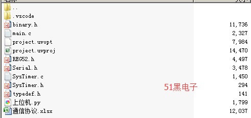
上图文件下载:
 C51_UART_EIO.zip
(24.26 KB, 下载次数: 19)
|