I have heard, even from a physicist, that it is impossible to build FM crystal radios. On the other hand some experimenters claim that they have built them. This argument intrigued me to try and build an FM crystal radio, which I have done successfully. To my surprise, the result is an astounding performer, pulling in four local stations in Tucson. When connected as a receiver to a good sound system the sound fidelity is as good or better than more expensive AM radios. In fact, it sounds "high-fidelity".
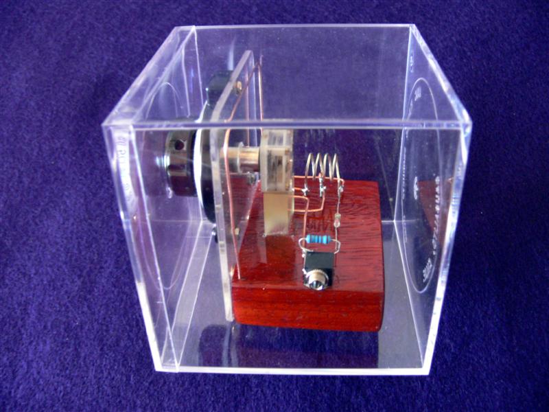
This picture shows the Solomon FM Crystal Set in an acrylic display case. I made the set specifically to fit inside this case (the case came first).
My definition of a crystal radio is one that is not powered, except by the radio transmission itself and employs a crystal detector. So, it should work without any batteries or AC power. An FM crystal receiver must be able to detect and receive FM signals well enough to be heard in earphones without any such extra power.
This FM receiver is an amazing performer. It has crystal clear reception (pun intended), good sensitivity, but only fair selectivity. This set was a discovery for me. I started out by designing and building the normal AM sets. Then one day while testing the "Mystery" set (see my other web links), to my surprise, in addition to the expected panoply of AM stations, I heard a very faint signal that I could not tune out. At first, it seemed too weak to identify. When I tuned out all the AM stations, I was astonished to hear the announcement "KiiM FM, 99.5"! This is a country music FM station here in Tucson. It was all over the dial, untunable, but the much louder AM signals masked it when they were tuned in.
I set myself the task of trying to improve the FM reception. I tried some simple circuit modifications that did not seem to improve anything. Then I connected a dipole antenna instead of the AM antenna I normally use. Suddenly, the FM signal was much clearer, although still weak. By using the audio output and sound system amplifier, I was even more amazed that four different FM stations came in loud (or rather medium) and clear. I found that changing the telescoping antenna length and position I could tune the stations in and out. They were KRQ, KLPX, KiiM, and KHYT all local FM stations with transmitters nearby. Their reception was also affected by the length and position of the audio output cable.
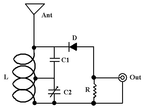
After doing some research, I discovered that there was a physical theory that claimed that FM reception was possible and even probable using the same circuit as an AM receiver. The theory is called "slope detection". So, I set out to find circuit improvements. A web search yielded little, mostly theory. But there was enough information that I thought I could make some modifications to the AM circuits to make them more tunable to FM signals and less tunable to AM. Since FM operates at higher frequencies, all I had to do, I thought, was make the coil and caps smaller. After much "tinkering" I arrived at the current circuit.
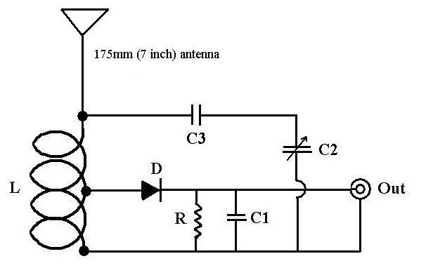
The circuit looks identical to a classic AM crystal circuit but is even simpler to build. The components were reduced in dimension to resonate at higher frequencies. This was done by experimenting with smaller and smaller coils and capacitors. The antenna is also much reduced in size (from that of AM) to resonate at higher frequencies (the antenna is crucial). The air variable capacitor I used has two trimmers in it which should be adjusted for best reception.I have found that a commonly available vernier dial and knob will fit the capacitor nicely. See end of article for a picture of the variable. C3 is a ceramic capacitor of 18 pf, but may be anywhere from 10 to 50pf. A detected FM signal is converted to AM due to an effect called slope detection that modulates amplitude.
This FM Crystal Set works best near the transmitter (I have not tested it beyond about 10 miles). Secondly, the sound level is quiet, especially without an amplifier. A quiet room is needed for listening with earphones. One must be willing to move the set around to find a location for the best reception of signals. However, in addition to listening with high impedance earphones (crystal or otherwise), the set can be connected directly to an audio amplifier's low level magnetic input which can then play amplified through a sound system at any volume -- sounds GREAT. In fact, I recommend starting tests with the FM crystal set by connecting it to the low-level phono inputs of a receiver or preamplifier. (Nowadays, many receivers don't even have a phono input!) That way you can crank up the volume, which makes it more likely to find the FM stations. If no signals are detected, I also recommend connecting an external "rabbit ear" antenna or hanging a short wire (12 inches or so) in various positions next to the internal antenna. The variable length of rabbitt ears can help to tune in stations.
No additional wiring or antenna is necessary (the antenna is optimized in length for FM.)
L - 4 turns #18 copper or silver wire, 12mm inside diameter, tapped at 2.5 turns
Ant - 7 inches of #18 bare copper wire
C1 - 18 pf ceramic capacitor
C2 - 50 pf air variable capacitor
D - 1N34 diode or rock crystal
R - 150K resistor
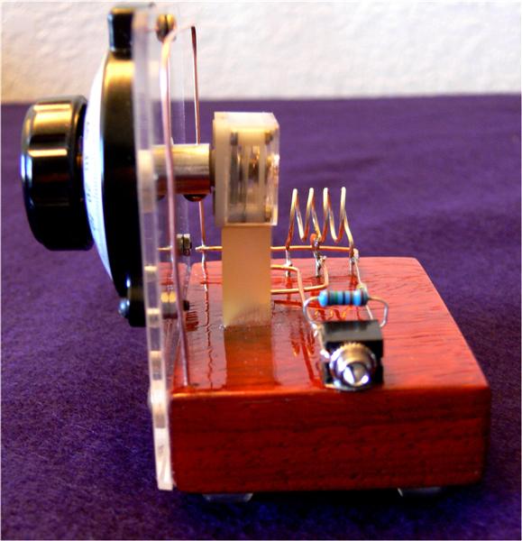
The diode is tapped directly to the antenna. The vernier dial fits directly on the tuning capacitor. The antenna parallels the perimeter of the acrylic face plate. "Military style" #18 AWG wiring is used without any insulation. It is important to keep the components physically close together. The component specifications are the same as in circuit #2. The coil is silver rather than copper, but copper does just as well. I think that the contrast of the silver and copper is beautiful. The coil was wrapped around a Sharpie Permanent Marker, then slipped off and expanded slightly. The wooden base is made from lacquered, polyurethane padouk.
I consider this set a work of art as well as science and think it is the most elegant crystal receiver I have created. I love the contrast of the silver coil, the copper antenna, the clear acrylic faceplate, the black vernier dial, the white and transparent variable capacitor, and the subtle colorings on the resistor, the diode, and the lucite base. Yet the circuit is so ridiculously simple that some will not believe it is possible without building it themselves. No shielding is necessary, and there is no problem with hand capacitance. However, the output cable position may affect reception sensitivity.
Photos of wired circuit
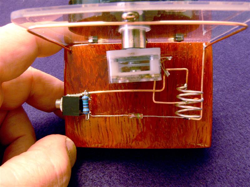
A hand is included in this photograph to show scale. Note the military style wiring, diode, and antenna. I wanted the wiring to create a modern design similar to a Mondrian painting. Not only is this set beautiful, it works! No power and no long antenna! It looks like a work of fiction.
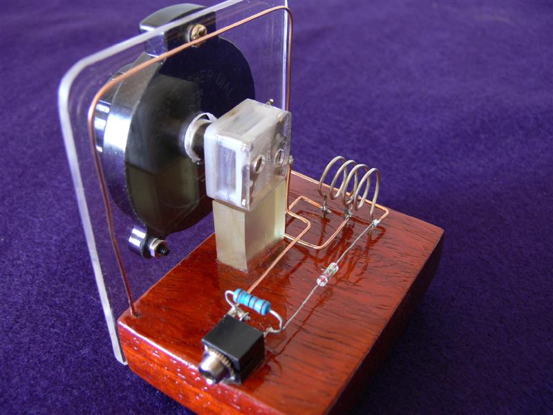
Is this thing imaginary -- science fiction? Well, imagination did play a part, but it is definitely not science fiction. This shot shows the elegance of the FM set best, I think. There is only one resistor and one fixed capacitor.
The inside of the tuning capacitor and the phono jack/output can be seen here. Can you spot the fixed ceramic capacitor? Note the polished edge of the face plate and the reflection in the wooden base.

A quarter-inch piece of lucite was fitted under the tuning capacitor to anchor it. Note the two tiny trimmers on the back of the tuning capacitor. Brass screws were used to enhance appearance.
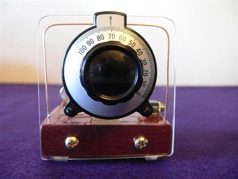
The vernier dial is large to accomodate ease of tuning, and the vernier makes it easy to separate stations. Two golden (brass) wood screws fix the face plate to the base. Holes for the face plate were made with special plastic drills, but ordinary drills may be used if drilled very SLOWLY. The knob is removable.

FM Crystal Circuit #2
L - 5 turns AWG#18 bare copper or silver wire, 12mm inside diameter, tapped at 2.5 turns
D - 1N34 or rock crystal diode
C1 - 82 pf capacitor
C2 - 80 pf air variable capacitor
C3 - 18 pf capacitor
R - 150K resistor
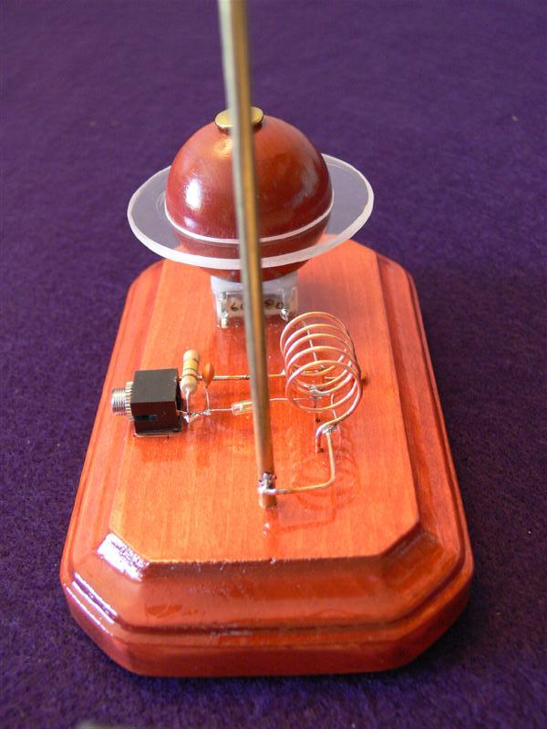
The following photographs show the circuit wired with the handmade Saturn Dial. and knob. It is perhaps not as visually striking as set No. 1, but it works just as well. In fact, this set was the original version. Notice that all the wiring and coil are copper.
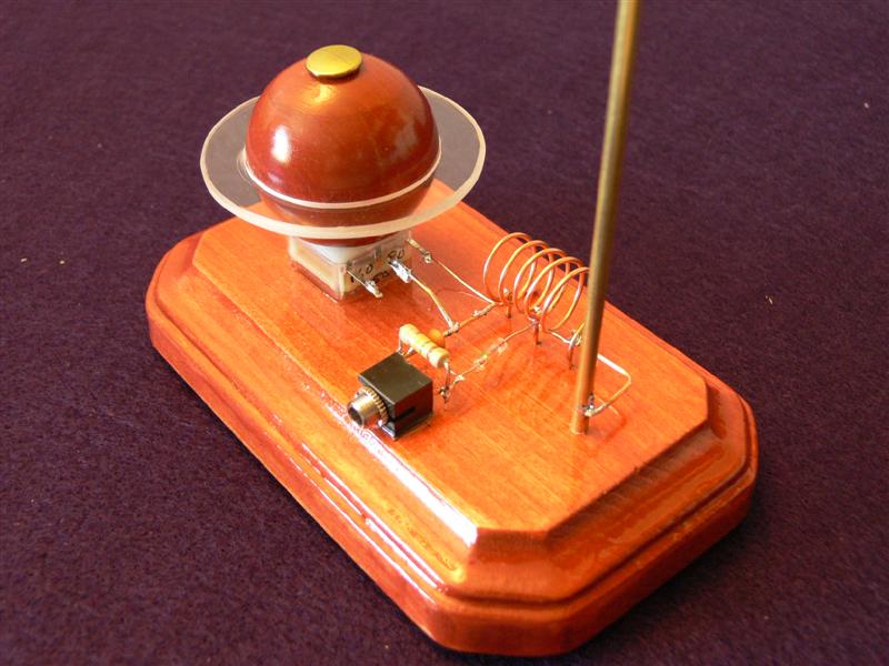
The Saturn dial and knob were fashioned from a "doll's head" from Michael's Arts and Crafts, a piece of lucite cut with two circle cutters, and a brass paper fastener. The knob is fixed to the tuning capacitor with a small machine screw that fits in the hole below the brass fastener. The most difficult part of this was fashioning "Saturn's rings". This must be done very carefully and slowly. The inside edge should be cut slightly undersized and then sanded with a drum sander to fit snugly. The outside edges can be sanded with fine sandpaper and polished with a plastic polisher.

The air variable capacitor may be obtained from Electronix Express at elexp Part number 14VCRF10-280P. The 80 pf side is recommended for the second circuit, contacts 2-3. Contacts 1 and 3 were used for the first circuit (50pf).
- OSC: 5-59 pf
- ANT: 5-142 pf
- OSC and ANT Trimmer 10pf range

 Home -- If you want to contact me go to the home page and go through the Music Clinic link. Home -- If you want to contact me go to the home page and go through the Music Clinic link.
|


 QQ好友和群
 QQ空间
QQ空间 腾讯微博
腾讯微博 腾讯朋友
腾讯朋友 收藏
收藏 淘帖
淘帖 顶
顶 踩
踩

