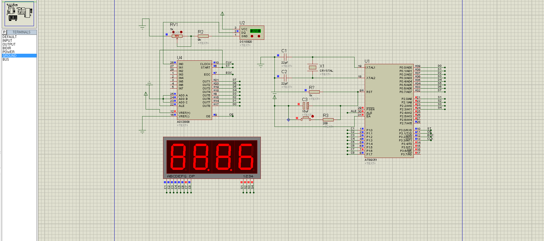
| DS18B20DQ端输出的是数字信号,怎么输入到0808区AD呢?概念完全错误,怪不得这么长时间没人理睬! |
| DS18B20DQ端输出的是数字信号,怎么输入到0808区AD呢?概念完全错误,怪不得这么长时间没人理睬! |
| 使用灌电流驱动,能提高驱动能力。 |
|
是LED驱动能力不够! 先弄清LED是共阴共阳,否则电流方向可能不正确,从而不显示。 然后,LED的Cx与Sx一高一低才能显示,电流从高流向低,但是提供电流的端口提供不了那么多的电流,也是不亮的。(查一下CPU手册,看看IO口输出最大电流是否能驱动LED的8个段。注:应当不能。) 第三,查一下LED的段电压降,如果压降太大(如,有的LED一个段是三个或更多的LED二极管串联而成的),也无法显示(驱动不了)。 |
| 硬件和软件相对应吗? |
| LZ,P0口要接上拉排阻,还有源代码与电路要相互匹配。 |
|
这是汇编程序 #include <reg51.H> #include <ctype.h> unsigned char code dispbitcode[]={0xfe,0xfd,0xfb,0xf7, 0xef,0xdf,0xbf,0x7f}; unsigned char code dispcode[]={0x3f,0x06,0x5b,0x4f,0x66, 0x6d,0x7d,0x07,0x7f,0x6f,0x00,0x40}; unsigned char dispbuf[8]={10,10,10,10,10,10,0,0}; unsigned char dispcount; unsigned char getdata; unsigned long temp; unsigned char i; bit sflag; sbit ST=P3^0; sbit OE=P3^1; sbit EOC=P3^2; sbit CLK=P3^3; sbit LED1=P3^6; sbit LED2=P3^7; sbit SPK=P3^5; void main(void) { ST=0; OE=0; TMOD=0x12; TH0=0x216; TL0=0x216; TH1=(65536-4000)/256; TL1=(65536-4000)%256; TR1=1; TR0=1; ET0=1; ET1=1; EA=1; ST=1; ST=0; getdata=148; while(1) { ; } } void t0(void) interrupt 1 using 0 { CLK=~CLK; } void t1(void) interrupt 3 using 0 { TH1=(65536-4000)/256; TL1=(65536-4000)%256; if(EOC==1) { OE=1; getdata=P0; OE=0; temp=(getdata*2350); temp=temp/128; if(temp<2732) { temp=2732-temp; sflag=1; } else { temp=temp-2732; sflag=0; } i=3; dispbuf[0]=10; dispbuf[1]=10; dispbuf[2]=10; if(sflag==1) { dispbuf[7]=11; } else { dispbuf[7]=10; } dispbuf[3]=0; dispbuf[4]=0; dispbuf[5]=0; dispbuf[6]=0; while(temp/10) { dispbuf[i]=temp%10; temp=temp/10; i++; } dispbuf[i]=temp; ST=1; ST=0; } P1=dispcode[dispbuf[dispcount]]; P2=dispbitcode[dispcount]; dispcount++; if(dispcount==8) { dispcount=0; } } |
 收藏
收藏 顶
顶 踩
踩

