目录
一、 设计任务与要求 3
二、设计思路 4
1.1设计方案 4
1.2设计要点 4
1.3工作原理 4
三、程序运行及结果 5
(1)分频模块 5
(2)秒模块 6
(3)分模块(minute) 8
(4)时模块(hour) 10
(5)数码显示驱动模块 12
(6)片选模块(sell) 13
(7)译码显示模块(display) 14
(8)报时模块(alart) 15
(9)六进制计数器模块(cnt6) 16
(10)两输入与模块(and2a) 17
(11)两输入或模块(or2a) 18
四、顶层电路设计及仿真结果与分析 19
五、心得体会 22
六、参考文献 23
七、 源程序 23
摘要:近年来随着数字技术的迅速发展,各种中、大规模集成电路在数字系统、控制系统、信号处理等方面都得到了广泛的应用。这就迫切要求理工科大学生熟悉和掌握常用中、大规模集成电路功能及其在实际中的应用方法,除通过实验教学培养数字电路的基本实验方法、分析问题和故障检查方法以及双踪示波器等常用仪器使用方法等基本电路的基本实验技能外,还必须培养大学生工程设计和组织实验能力。
本次设计的目的在于培养学生对基本电路的应用和掌握,使学生在实验原理的指导下,初步具备基本电路的分析和设计能力,并掌握其应用方法;自行拟定实验步骤,检查和排除故障 、分析和处理实验结果及撰写实验报告的能力。综合实验的设计目的是培养学生初步掌握小型数字系统的设计能力,包括选择设计方案,进行电路设计、安装、调试等环节,运用所学知识进行工程设计、提高实验技能的实践。数字电子钟是一种计时装置,它具有时、分、秒计时功能和显示时间功能;具有整点报时功能。 本次设计我查阅了大量的文献资料,学到了很多关于数字电路方面的知识,并且更加巩固和掌握了课堂上所学的课本知识,使自己对数字电子技术有了更进一步的认识和了解。 基本功能:能进行正常的时、分、秒计时功能,分别由6个数码管显示24小时,60分钟,60秒钟的计数器显示。 附加功能:1)能利用硬件部分按键实现“校时”“校分”“清零”功能; 2)能利用蜂鸣器做整点报时:当计时到达59’59’’时开始报时,鸣叫时间1秒钟; 3)定时闹铃:本设计中设置的是在七点时进行闹钟功能,鸣叫过程中,能够进行中断闹铃工作。 二、设计思路 1.1设计方案 1、时钟功能,具有显示时、分、秒的功能; 2、具有整点报时功能,在整点时使用蜂鸣器进行报时,具有闹钟功能,鸣叫过程中,具有中断闹铃功能。 1.2设计要点 数字钟一般是由振荡器、分频器、计数器、译码器、显示器等几部分组成。这些都是数字电路中应用最广泛的基本电路,本设计分模块设计实现各部分功能,采用软件编程控制FPGA芯片内部产生振动周期为1s的脉冲。并将信号送入计数器进行计算,并把累加的结果以“时”、“分”、“秒”的数字显示出来。“秒”的显示由两级计数器和译码器组成的六十进制计数电路实现;“分”的显示电路“秒”相同,“时”的显示由两级计数器和译码器组成的二十四进制电路来实现。所有计时结果由六位数码管显示。 1.3工作原理 数字电子钟由振荡器、分频器 计数器、译码显示、报时等电路组成。振荡器产生稳定的高频脉冲信号,作为数字钟的时间基准,然后经过分频器输出标准秒脉冲。秒计数器满60后向分计数器进位,分计数器满60后向小时计数器进位,小时计数器按照“24翻1”规律计数。计满后各计数器清零,重新计数。计数器的输出分别经译码器送数码管显示,计时出现误差时,可以用校时电路“校时”“校分”“清零”。秒脉冲可以通过分频电路得到。通过报时设计模块可以实现整点报时及定时闹铃,译码显示由七段译码器完成,显示由数码管构成,采用的是动态显示方式。数码管动态显示:动态扫描电路将计数器输出的8421BGD码转换为数码管需要的逻辑状态,并且输出数码管的片选信号和为选信号。所谓动态扫描显示方式是在显示某一位LED 显示块的数据的时候,让其它位不显示,然后再显示下一位的数据。只要保证每一位显示的时间间隔不要太大,利用人眼的视觉暂留的现象,就可以造成各位数据同时显示的假象。一般每一位的显示时间为1~10ms。 三、程序运行及结果 (1)分频模块(fenpin) 1)程序: library ieee; use ieee.std_logic_1164.all; entity fenpin is port(clk6:in std_logic; q1000,q5,q1:out std_logic); end fenpin; architecture ccc_arc of fenpin is signal x:std_logic; begin process(clk6) variable cnt:integer range 0 to 24999; begin if clk6'event and clk6='1' then if cnt<24999 then cnt:=cnt+1; else cnt:=0; x<=not x; end if; end if; end process; q1000<=x; process(x) variable cnt2:integer range 0 to 999; variable y:std_logic; begin if x'event and x='1' then if cnt2<999 then cnt2:=cnt2+1; q1<='0'; else cnt2:=0; q1<='1'; end if; end if; if x'event and x='1' then y:=not y; end if; q5<=y; end process; end ccc_arc; 2)仿真波形: 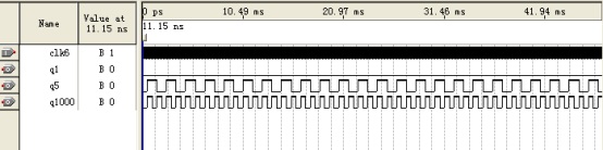
- 仿真结果分析:产生用于计时,扫描输入,扫描显示,以及蜂鸣器所需的各个频率的信号。
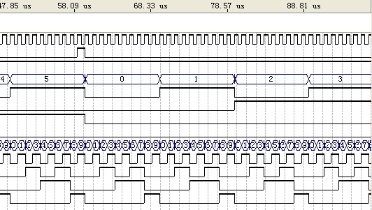
(2)秒模块(second) 1)程序: library ieee; use ieee.std_logic_1164.all; use ieee.std_logic_unsigned.all; entity second is port (clk1,en1:in std_logic; qa:out std_logic_vector(3 downto 0); co1:out std_logic; qb:out std_logic_vector(3 downto 0)); end second; architecture cc of second is signal cout2,cout1:std_logic_vector(3 downto 0); signal mm: std_logic; begin process(clk1,en1) begin if en1='1' then cout2<="0000";cout1<="0000"; elsif (clk1'event and clk1='1')then if (cout2=5 and cout1=8) then cout2<=cout2;cout1<=cout1+1;mm<='1'; elsif (cout2=5 and cout1=9) then cout2<="0000";cout1<="0000";mm<='0'; else if (cout1=9) then cout2<=cout2+1;cout1<="0000";mm<='0'; else cout2<=cout2;cout1<=cout1+1;mm<='0'; end if; end if; end if; end process; co1<=mm; qa<=cout2; qb<=cout1; end cc; 2)仿真波形: 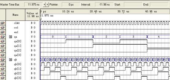

- 仿真结果分析:该模块实际是一个六十进制计数器,而六十秒为一分钟,故用此模块可以作为秒部分设计,通过观察可知,仿真波形是正确可行的。
(3)分模块(minute) 1)程序: library ieee; use ieee.std_logic_1164.all; use ieee.std_logic_unsigned.all; entity minute is port (clk2,en2:in std_logic; qc:out std_logic_vector(3 downto 0); co2:out std_logic; qd:out std_logic_vector(3 downto 0)); end minute; architecture bb of minute is signal cout2,cout1:std_logic_vector(3 downto 0); signal cc:std_logic; begin process(clk2,en2) begin if en2='1' then if (clk2'event and clk2='1')then if (cout2=5 and cout1=8) then cout2<=cout2;cout1<=cout1+1;cc<='1'; elsif (cout2=5 and cout1=9) then cout2<="0000";cout1<="0000";cc<='0'; else if (cout1=9) then cout2<=cout2+1;cout1<="0000";cc<='0'; else cout2<=cout2;cout1<=cout1+1;cc<='0'; end if; end if; end if; end if; end process; co2<=cc; qc<=cout2; qd<=cout1; end bb 2)仿真波形: 
- 仿真结果分析:此模块实际也是一个六十进制的计数器模块,六十分钟即为一个小时,用此模块就成功解决了分设计模块这个难题。从仿真波形可知,该设计时正确的。
(4)时模块(hour) 1)程序: library ieee; use ieee.std_logic_1164.all; use ieee.std_logic_unsigned.all; entity hour is port (clk3,en3:in std_logic; qe:out std_logic_vector(3 downto 0); qf:out std_logic_vector(3 downto 0)); end hour; architecture aa of hour is signal cout2,cout1:std_logic_vector(3 downto 0); begin process(clk3,en3) begin if en3='1' then if (clk3'event and clk3='1')then if (cout2=2 and cout1=3) then cout2<="0000";cout1<="0000"; else if (cout1=9) then cout2<=cout2+1;cout1<="0000"; else cout2<=cout2;cout1<=cout1+1; end if; end if; end if; end if; end process; qe<=cout2; qf<=cout1; end aa; 2)仿真波形: 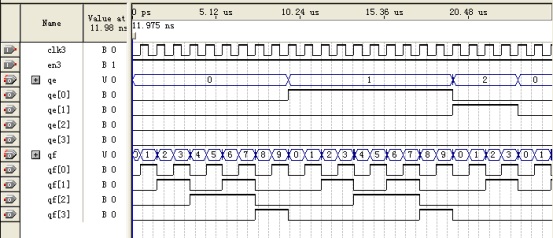

- 仿真结果分析:这是一个24计数器,用来表示24小时,通过波形可知,程序设计正确,正常计时是每次清零后从00:00:00开始计时的,若要从预置时间开始,可以通过“校时”“校分”“清零”三个按键调整时间。
(5)数码显示驱动模块 1)程序: library ieee; use ieee.std_logic_1164.all; use ieee.std_logic_unsigned.all; entity hhh is port(n1,n2,n3,n4,n5,n6:in std_logic_vector(3 downto 0); a:in std_logic_vector(2 downto 0); qqq:out std_logic_vector(3 downto 0)); end hhh; architecture dd of hhh is begin with a select qqq<=n1 when "000", n2 when "001", n3 when "010", n4 when "011", n5 when "100", n6 when "101", "0000" when others; end dd; 2)仿真波形: 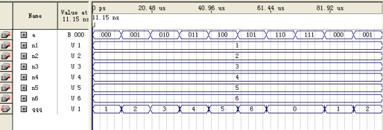
- 仿真结果分析:其实这是一个选择器,从波形图可以很容易看出来。它是用来选择需要显示的数字,比如秒的十位,就会选择n1到译码显示器显示出来,具备驱动数码管的作用!
(6)片选模块(sell) 1)程序: library ieee; use ieee.std_logic_1164.all; use ieee.std_logic_unsigned.all; entity ggg is port(m:in std_logic_vector(2 downto 0); b:out std_logic_vector(5 downto 0)); end ggg; architecture ee of ggg is begin with m select b<="100000" when "000", "010000" when "001", "001000" when "010", "000100" when "011", "000010" when "100", "000001" when "101", "000000" when others; end ee; 2)仿真波形: 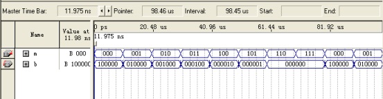
- 仿真结果分析:设置时间时将所需的数据传给显示模块,当设置闹铃时将数据传给闹钟和显示模块。
(7)译码显示模块(display) 1)程序: library ieee; use ieee.std_logic_1164.all; use ieee.std_logic_unsigned.all; entity decoder is port(x:in std_logic_vector(3 downto 0); y:out std_logic_vector(6 downto 0)); end decoder; architecture one of decoder is begin with x select y<="1111110" when "0000", "0110000" when "0001", "1101101" when "0010", "1111001" when "0011", "0110011" when "0100", "1011011" when "0101", "1011111" when "0110", "1110000" when "0111", "1111111" when "1000", "1111011" when "1001", "0000000" when others; end one; 2)仿真波形: 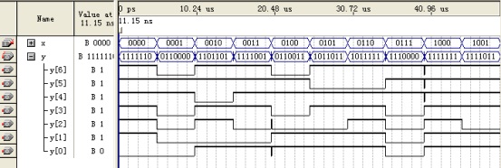
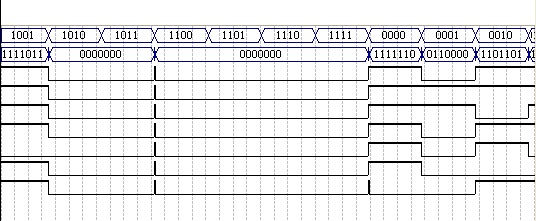
- 仿真结果分析:此模块是用来显示时间的,采用动态显示方式。
(8)报时模块(alart) 1) 程序: library ieee; use ieee.std_logic_1164.all; entity sst is port(h1,h0,m1,m0,s1,s0:in std_logic_vector(3 downto 0); clk4:in std_logic; q500:out std_logic); end sst; architecture sss of sst is begin process(clk4,m1,m0,s1,s0) begin if (clk4'event and clk4='1') then if ((h1="0000" and h0="0111" and m1="0000" and m0="0000") or (m1="0101" and m0="1001" and s1="0101" and s0="1001"))then q500<='1'; else q500<='0'; end if; end if; end process; end sss; 2) 仿真波形: 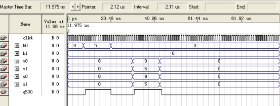
- 仿真结果分析:通过观察波形可知,当时钟时间与整点或闹铃预设时间相同时,给出一个脉冲信号,使蜂鸣器鸣叫,实现整点报时和定时闹铃功能。
(9)六进制计数器模块(cnt6) 1)程序: library ieee; use ieee.std_logic_1164.all; use ieee.std_logic_unsigned.all; entity cnt6 is port (clk5:in std_logic; n:out std_logic_vector(2 downto 0)); end cnt6; architecture behav of cnt6 is signal q1:std_logic_vector(2 downto 0); begin process(clk5) begin if clk5'event and clk5='1' then if q1<5 then q1<=q1+1; else q1<=(others=>'0'); end if; end if; end process; n<=q1; end behav; 2)仿真波形: 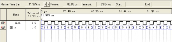
- 仿真结果分析:很明显可以看出这是一个简单的六进制计数器。它与3-6译码器配合作用产生片选信号。
(10)两输入与模块(and2a) 1)程序: library ieee; use ieee.std_logic_1164.all; entity anda is port (a1,b1:in std_logic; y:out std_logic); end anda; architecture an of anda is begin y<=a1 and b1; end an; 2)仿真波形: 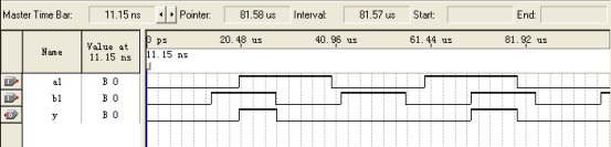
3) 仿真结果分析:经观察波形,程序正确。该与门的两个输入端分别为秒模块和分模块的进位输出信号,当它们均为高电平时,时模块使能端即为高电平,时模块工作。 (11)两输入或模块(or2a) 1)程序: library ieee; use ieee.std_logic_1164.all; entity or_1 is port (a1,b1:in std_logic; y:out std_logic); end or_1; architecture oo of or_1 is begin y<=a1 or b1; end oo; 2)仿真波形: 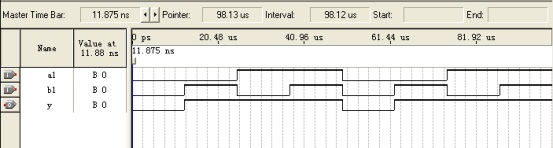
3) 仿真结果分析:在整个数字钟程序设计中,两处用到两输入或门。一处是分模块,或门两输入分别是秒模块的进位输出信号和外部校分信号,任一一个信号为高电平,分模块使能端就为高电平,分模块工作。另一处是在时模块的使能端,它受分模块进位输出和外部校时信号输入的控制,只要其一位高电平,时模块都将工作。 四、顶层电路设计及仿真结果与分析 - library ieee;
- use ieee.std_logic_1164.all;
- entity digital_clock is
- port(clk,sa,sb,sc:in std_logic;
- q1:out std_logic;
- r:out std_logic_vector(5 downto 0);
- q0:out std_logic_vector(6 downto 0));
- end digital_clock;
- architecture main of digital_clock is
- component anda
- port(a1,b1:in std_logic;
- y:out std_logic);
- end component;
- component or_1
- port(a1,b1:in std_logic;
- y:out std_logic);
- end component;
- component fenpin
- port(clk6:in std_logic;
- q1000,q1,q5:out std_logic);
- end component;
- component hour
- port (clk3,en3:in std_logic;
- qe:out std_logic_vector(3 downto 0);
- qf:out std_logic_vector(3 downto 0));
- end component;
- component minute
- port (clk2,en2:in std_logic;
- qc:out std_logic_vector(3 downto 0);
- co2:out std_logic;
- qd:out std_logic_vector(3 downto 0));
- end component;
- component second
- port (clk1,en1:in std_logic;
- qa:out std_logic_vector(3 downto 0);
- co1:out std_logic;
- qb:out std_logic_vector(3 downto 0));
- end component;
- component sst is
- port(h1,h0,m1,m0,s1,s0:in std_logic_vector(3 downto 0);
- clk4:in std_logic;
- q500:out std_logic);
- end component;
- component hhh
- port(n1,n2,n3,n4,n5,n6:in std_logic_vector(3 downto 0);
- a:in std_logic_vector(2 downto 0);
- qqq:out std_logic_vector(3 downto 0));
- end component;
- component ggg
- port(m:in std_logic_vector(2 downto 0);
- b:out std_logic_vector(5 downto 0));
- end component;
- component cnt6 is
- port (clk5:in std_logic;
- n:out std_logic_vector(2 downto 0));
- end component;
- component decoder
- port(x:in std_logic_vector(3 downto 0);
- y:out std_logic_vector(6 downto 0));
- end component;
- signal a,b,c,h, i,j,z:std_logic;
- signal k,l,e,f,u,v,t:std_logic_vector(3 downto 0);
- signal s: std_logic_vector(2 downto 0);
- begin
- u1:fenpin port map(clk6=>clk,q1=>h,q1000=>z);
- u2:second port map(clk1=>h,en1=>sc,qa=>k,qb=>l,co1=>I);
- u0:or_1 port map(a1=>i,b1=>sb,y=>a);
- u3:minute port map(clk2=>h,en2=>a,qc=>e,qd=>f,co2=>j);
- u30:anda port map(a1=>i,b1=>j,y=>b);
- u31:or_1 port map(a1=>b,b1=>sa,y=>c);
- u4:hour port map(clk3=>h,en3=>c,qe=>u,qf=>v);
- u5:sst port map(h1=>u,h0=>v,m1=>e,m0=>f,s1=>k,s0=>l,clk4=>h,q500=>q1);
- u6:hhh port map(n1=>k,n2=>l,n3=>e,n4=>f,n5=>u,n6=>v,qqq=>t,a=>s);
- u7:ggg port map(b=>r,m=>s);
- u8:cnt6 port map(n=>s,clk5=>z);
- u9:decoder port map(x=>t,y=>q0);
- end architecture main;
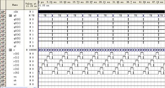
3)仿真结果分析:本次试验给出的频率是50MHZ,用QUARTUS-2软件把数字钟的全部工作过程记录下来不容易,故这幅图只是其工作的一小部分。将程序下载到FPGA芯片中,并与硬件部分对应连接好,可以验证到我们所预期的所有功能,故可知该顶层文件是正确的,每一个模块的功能也都是正确的,模块之间的连接也都是正确的。 在软件调试仿真过程中,我们以参考资料上的程序为模板,依据个人的需要添加修改各个功能模块,尽管有模板作为参考,仿真过程中还是出了很多的问题,例如在做数码管动态显示中,我们采用了NPN型9013晶体三极管作为数码管的接地驱动,这里的片选信号应该是高电平有效,我们原程序是低电平,经过多次的和其他组的学习交流中,找到了这个错误。解决分频问题中,我们也在分频模块中做了修改,得到我们所需要的频率。 五、心得体会 经过这次的数字电路课程设计,我个人得到了不少的收获,一方面加深了我对课本理论的认识,另一方面也提高了实验操作能力。现在我总结了以下的体会和经验。 这次的课程设计跟我们以前做的不同,因为我觉得这次我是真真正正的自己亲自去完成。所以是我觉得这次实验最宝贵,最深刻的。就是设计的过程全是我们学生自己动手来完成的,这样,我们就必须要弄懂一个电路的原理。在这里我深深体会到哲学上理论对实践的指导作用:弄懂实验原理,而且体会到了实验的操作能力是靠自己亲自动手,亲自开动脑筋,亲自去请教别人才能得到提高的。 我们做实验绝对不能人云亦云,要有自己的看法,这样我们就要有充分的准备,若是做了也不知道是个什么实验,那么做了也是白做。实验总是与课本知识相关的,有了课本的知识,我们才能编写出自己需要的程序,实现自己预期的功能。 我们做实验不要一成不变和墨守成规,应该有改良创新的精神。实际上,在弄懂了实验原理的基础上,我们的时间是充分的,做实验应该是游刃有余的,如果说创新对于我们来说是件难事,那改良总是有可能的。数字时钟大体看上去很简单,但其中的可变的地方还是有很多的,譬如说整点报时功能,报时持续的时间长短就是一个可变的地方。 在实验的过程中我们要培养自己的独立分析问题,和解决问题的能力。在编程过程中,我们也遇到了很多的问题,就之前提到的动态扫描驱动问题,如果一味的去遵循资料上的程序的话,那整个设计将会失败,只有不断的学习研究,才能解决问题。 这次的课程设计,我的收获很多,就我本身来说,不但对理论知识有了更加深的理解,对于实际的操作和也有了质的飞跃。经过这次的实验,我们整体对各个方面都得到了不少的提高,团队的合作意识也增强了很多。 六、参考资料: 付家才 .《 EDA工程实践技术 》.化学工业出版社.2004年12月 陈忠平 .《 基于Quartus II的FPGA/CPLD设计与实践 》.北京电子工业出版社.2010年4月 - library ieee;
- use ieee.std_logic_1164.all;
- entity fenpin is
- port(clk6:in std_logic;
- q1000,q5,q1:out std_logic);
- end fenpin;
- architecture ccc_arc of fenpin is
- signal x:std_logic;
- begin
- process(clk6)
- variable cnt:integer range 0 to 24999;
- begin
- if clk6'event and clk6='1' then
- if cnt<24999 then
- cnt:=cnt+1;
- else
- cnt:=0;
- x<=not x;
- end if;
- end if;
- end process;
- q1000<=x;
- process(x)
- variable cnt2:integer range 0 to 999;
- variable y:std_logic;
- begin
- if x'event and x='1' then
- if cnt2<999 then
- cnt2:=cnt2+1;
- q1<='0';
- else
- cnt2:=0;
- q1<='1';
- end if;
- end if;
- if x'event and x='1' then
- y:=not y;
- end if;
- q5<=y;
- end process;
- end ccc_arc;
- library ieee;
- use ieee.std_logic_1164.all;
- use ieee.std_logic_unsigned.all;
- entity second is
- port (clk1,en1:in std_logic;
- qa:out std_logic_vector(3 downto 0);
- co1:out std_logic;
- qb:out std_logic_vector(3 downto 0));
- end second;
- architecture cc of second is
- signal cout2,cout1:std_logic_vector(3 downto 0);
- signal mm: std_logic;
- begin
- process(clk1,en1)
- begin
- if en1='1' then
- cout2<="0000";cout1<="0000";
- elsif (clk1'event and clk1='1')then
- if (cout2=5 and cout1=8) then cout2<=cout2;cout1<=cout1+1;mm<='1';
- elsif (cout2=5 and cout1=9) then cout2<="0000";cout1<="0000";mm<='0';
- else if (cout1=9) then cout2<=cout2+1;cout1<="0000";mm<='0';
- else cout2<=cout2;cout1<=cout1+1;mm<='0';
- end if;
- end if;
- end if;
- end process;
- co1<=mm;
- qa<=cout2;
- qb<=cout1;
- end cc;
- library ieee;
- use ieee.std_logic_1164.all;
- use ieee.std_logic_unsigned.all;
- entity minute is
- port (clk2,en2:in std_logic;
- qc:out std_logic_vector(3 downto 0);
- co2:out std_logic;
- qd:out std_logic_vector(3 downto 0));
- end minute;
- architecture bb of minute is
- signal cout2,cout1:std_logic_vector(3 downto 0);
- signal cc:std_logic;
- begin
- process(clk2,en2)
- begin
- if en2='1' then
- if (clk2'event and clk2='1')then
- if (cout2=5 and cout1=8) then cout2<=cout2;cout1<=cout1+1;cc<='1';
- elsif (cout2=5 and cout1=9) then cout2<="0000";cout1<="0000";cc<='0';
- else if (cout1=9) then cout2<=cout2+1;cout1<="0000";cc<='0';
- else cout2<=cout2;cout1<=cout1+1;cc<='0';
- end if;
- end if;
- end if;
- end if;
- end process;
- co2<=cc;
- qc<=cout2;
- qd<=cout1;
- end bb
- library ieee;
- use ieee.std_logic_1164.all;
- use ieee.std_logic_unsigned.all;
- entity hour is
- port (clk3,en3:in std_logic;
- qe:out std_logic_vector(3 downto 0);
- qf:out std_logic_vector(3 downto 0));
- end hour;
- architecture aa of hour is
- signal cout2,cout1:std_logic_vector(3 downto 0);
- begin
- process(clk3,en3)
- begin
- if en3='1' then
- if (clk3'event and clk3='1')then
- if (cout2=2 and cout1=3) then cout2<="0000";cout1<="0000";
- else if (cout1=9) then cout2<=cout2+1;cout1<="0000";
- else cout2<=cout2;cout1<=cout1+1;
- end if;
- end if;
- end if;
- end if;
- end process;
- qe<=cout2;
- qf<=cout1;
- end aa;
- library ieee;
- use ieee.std_logic_1164.all;
- use ieee.std_logic_unsigned.all;
- entity hhh is
- port(n1,n2,n3,n4,n5,n6:in std_logic_vector(3 downto 0);
- a:in std_logic_vector(2 downto 0);
- qqq:out std_logic_vector(3 downto 0));
- end hhh;
- architecture dd of hhh is
- begin
- with a select
- qqq<=n1 when "000",
- n2 when "001",
- n3 when "010",
- n4 when "011",
- n5 when "100",
- n6 when "101",
- "0000" when others;
- end dd;
- library ieee;
- use ieee.std_logic_1164.all;
- use ieee.std_logic_unsigned.all;
- entity ggg is
- port(m:in std_logic_vector(2 downto 0);
- b:out std_logic_vector(5 downto 0));
- end ggg;
- architecture ee of ggg is
- begin
- with m select
- b<="100000" when "000",
- "010000" when "001",
- "001000" when "010",
- "000100" when "011",
- "000010" when "100",
- "000001" when "101",
- "000000" when others;
- end ee;
- library ieee;
- use ieee.std_logic_1164.all;
- use ieee.std_logic_unsigned.all;
- entity decoder is
- port(x:in std_logic_vector(3 downto 0);
- y:out std_logic_vector(6 downto 0));
- end decoder;
- architecture one of decoder is
- begin
- with x select
- y<="1111110" when "0000",
- "0110000" when "0001",
- "1101101" when "0010",
- "1111001" when "0011",
- "0110011" when "0100",
- "1011011" when "0101",
- "1011111" when "0110",
- "1110000" when "0111",
- "1111111" when "1000",
- "1111011" when "1001",
- "0000000" when others;
- end one;
- library ieee;
- use ieee.std_logic_1164.all;
- entity sst is
- port(h1,h0,m1,m0,s1,s0:in std_logic_vector(3 downto 0);
- clk4:in std_logic;
- q500:out std_logic);
- end sst;
- architecture sss of sst is
- begin
- process(clk4,m1,m0,s1,s0)
- begin
- if (clk4'event and clk4='1') then
- if ((h1="0000" and h0="0111" and m1="0000" and m0="0000")
- or (m1="0101" and m0="1001" and s1="0101" and s0="1001"))then
- q500<='1';
- else
- q500<='0';
- end if;
- end if;
- end process;
- end sss;
- library ieee;
- use ieee.std_logic_1164.all;
- use ieee.std_logic_unsigned.all;
- entity cnt6 is
- port (clk5:in std_logic;
- n:out std_logic_vector(2 downto 0));
- end cnt6;
- architecture behav of cnt6 is
- signal q1:std_logic_vector(2 downto 0);
- begin
- process(clk5)
- begin
- if clk5'event and clk5='1' then
- if q1<5 then q1<=q1+1;
- else q1<=(others=>'0');
- end if;
- end if;
- end process;
- n<=q1;
- end behav;
- library ieee;
- use ieee.std_logic_1164.all;
- entity anda is
- port (a1,b1:in std_logic;
- y:out std_logic);
- end anda;
- architecture an of anda is
- begin
- y<=a1 and b1;
- end an;
- library ieee;
- use ieee.std_logic_1164.all;
- entity or_1 is
- port (a1,b1:in std_logic;
- y:out std_logic);
- end or_1;
- architecture oo of or_1 is
- begin
- y<=a1 or b1;
- end oo;
- library ieee;
- use ieee.std_logic_1164.all;
- entity digital_clock is
- port(clk,sa,sb,sc:in std_logic;
- q1:out std_logic;
- r:out std_logic_vector(5 downto 0);
- q0:out std_logic_vector(6 downto 0));
- end digital_clock;
- architecture main of digital_clock is
- component anda
- port(a1,b1:in std_logic;
- y:out std_logic);
- end component;
- component or_1
- port(a1,b1:in std_logic;
- y:out std_logic);
- end component;
- component fenpin
- port(clk6:in std_logic;
- q1000,q1,q5:out std_logic);
- end component;
- component hour
- port (clk3,en3:in std_logic;
- qe:out std_logic_vector(3 downto 0);
- qf:out std_logic_vector(3 downto 0));
- end component;
- component minute
- port (clk2,en2:in std_logic;
- qc:out std_logic_vector(3 downto 0);
- co2:out std_logic;
- qd:out std_logic_vector(3 downto 0));
- end component;
- component second
- port (clk1,en1:in std_logic;
- qa:out std_logic_vector(3 downto 0);
- co1:out std_logic;
- qb:out std_logic_vector(3 downto 0));
- end component;
- component sst is
- port(h1,h0,m1,m0,s1,s0:in std_logic_vector(3 downto 0);
- clk4:in std_logic;
- q500:out std_logic);
- end component;
- component hhh
- port(n1,n2,n3,n4,n5,n6:in std_logic_vector(3 downto 0);
- a:in std_logic_vector(2 downto 0);
- qqq:out std_logic_vector(3 downto 0));
- end component;
- component ggg
- port(m:in std_logic_vector(2 downto 0);
- b:out std_logic_vector(5 downto 0));
- end component;
- component cnt6 is
- port (clk5:in std_logic;
- n:out std_logic_vector(2 downto 0));
- end component;
- component decoder
- port(x:in std_logic_vector(3 downto 0);
- y:out std_logic_vector(6 downto 0));
- end component;
- signal a,b,c,h, i,j,z:std_logic;
- signal k,l,e,f,u,v,t:std_logic_vector(3 downto 0);
- signal s: std_logic_vector(2 downto 0);
- begin
- u1:fenpin port map(clk6=>clk,q1=>h,q1000=>z);
- u2:second port map(clk1=>h,en1=>sc,qa=>k,qb=>l,co1=>I);
- u0:or_1 port map(a1=>i,b1=>sb,y=>a);
- u3:minute port map(clk2=>h,en2=>a,qc=>e,qd=>f,co2=>j);
- u30:anda port map(a1=>i,b1=>j,y=>b);
- u31:or_1 port map(a1=>b,b1=>sa,y=>c);
- u4:hour port map(clk3=>h,en3=>c,qe=>u,qf=>v);
- u5:sst port map(h1=>u,h0=>v,m1=>e,m0=>f,s1=>k,s0=>l,clk4=>h,q500=>q1);
- u6:hhh port map(n1=>k,n2=>l,n3=>e,n4=>f,n5=>u,n6=>v,qqq=>t,a=>s);
- u7:ggg port map(b=>r,m=>s);
- u8:cnt6 port map(n=>s,clk5=>z);
- u9:decoder port map(x=>t,y=>q0);
- end architecture main;
以上的Word格式文档51黑下载地址:
 数电课程设计——基于fpga的数字时钟的设计.doc
(364.62 KB, 下载次数: 81)
数电课程设计——基于fpga的数字时钟的设计.doc
(364.62 KB, 下载次数: 81)
|


 QQ好友和群
 QQ空间
QQ空间 腾讯微博
腾讯微博 腾讯朋友
腾讯朋友 收藏
收藏 淘帖
淘帖 顶
顶 踩
踩

