--部分模块代码如下:完整代码及文档说明附页下载,工程用quratus 13.1以上打开
2.设计内容
3. 系统的主要功能及使用方法
4. 数字电子钟的VHDL设计
4.1设计思想
4.2设计电路图
4.3模块说明
4.3.1 分频器
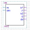
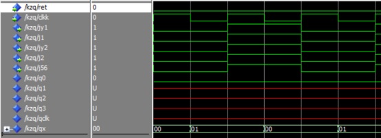
4.3.2功能选择器
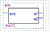
4.3.3一输入二输出器
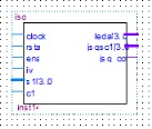
4.3.4计数器1至计数器6
4.3.5计数器(1-3)的校正器、计数器(4-6)的校正器
4.3.6防止异步清零器、异步清零器、数码管选择器、led灯选择器、数码管显示时间器
4.3.7顶层文件
4.4硬件配置调试
4.4.1硬件要求
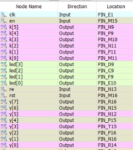
4.4.2引脚绑定
4.2.3现象说明
5. 实验总结
5.1错误和解决方法
时钟是我们日常生活中必备的生活用品之一。而数字时钟的出现更是给人们的生产生活带来了极大的便利。钟表的数字化给人们生产生活带来了极大的方便而且大大地扩展了钟表原先的报时功能。诸如定时自动报警、按时自动打铃、时间程序自动控制、定时广播、定时启闭电路、定时开关烘箱、通断动力设备,甚至各种定时电气的自动启用等,所有这些,都是以钟表数字化为基础的。因此,研究数字钟及扩大其应用,有着非常现实的意义。 本次设计的目的就是在掌握EDA实验开发系统的初步使用基础上,学习较复杂数字电路系统的设计。EDA技术为数字类产品提供了一个非常简便实用的开发平台。随着EDA技术的快速发展,数字时钟的应用越来越广泛,并且它在功能外观方面也有了很大的改善和提高。本文就是基于EDA技术的基础知识,利用Quartus2软件再现一个具有传统时钟功能的数字时钟。 2.设计内容设计内容: 设计一个电子钟,要求可以显示时、分、秒,用户可以设置时间 设计具体包含的模块内容如下: 要求: (1)根据系统设计要求,采用自顶向下的方法,划分系统主要模块,画出整体设计原理框图。 (2)根据工作原理、用硬件描述语言对设计内容实现,列出设计程序清单,给出仿真波形图和调试中存在问题及解决方法。 (3)设计内容下载至目标芯片,在ALINX开发板上进行功能验证。 (4)谈谈该课题的设计中遇到的问题,获得哪些技能和体会,以及建设性意见。 3.系统的主要功能及使用方法该数字钟有如下几个功能 - 数字可以显示当前时间的秒、分、时,或者作为秒表使用,且每过一秒4个led灯就交替循环亮;
- 一个功能选择按键(key0),用于切换不同状态:计时、或者对时、分秒的进行校正和更改。
(3)两个按键(key1和key2),每个键根据功能选择键(key0)有不同同的作用; ①计时时:key1键为时钟使能键,key2为对秒、分、时同时进行异步清零; ②校正时:key1键为对秒和分的个位进行校正,key2键为对分的十位和时进行校正 4.数字电子钟的VHDL设计
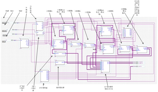
4.1设计思想本设计采用层次描述方式,采用自顶向下的方法,划分系统主要模块,画出整体设计原理框图。设计几个具有各自功能的元件,然后将他们级连得到一个可预制的数字钟。本设计具有分频器、功能选择器、一输入二输出器,计数器1至计数器6、计数器(1-3)的校正器,计数器(4-6)的校正器、防止异步清零器、异步清零器、数码管选择器、led灯选择器、数码管显示时间器,一共16个模块,最后把各个元件连接起来。
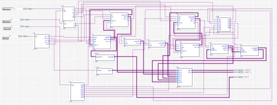
4.2设计电路图 图4.2.1 电路原理图 图4.2.2 电路总体模块名称图 4.3模块说明
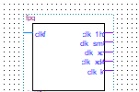
4.3.1 分频器将50mHz的时钟源分频为时间计时频率1秒、数码管扫描频率1毫秒、key1消抖频率0.3秒、key2消抖频率0.3秒、 key0消抖频率0.3秒(如图由上到下)。 图4.3.1a 分频器模块
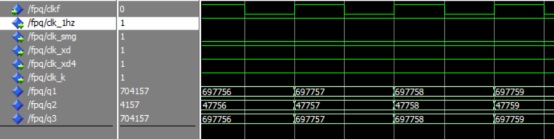
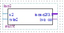
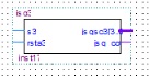
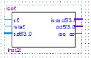
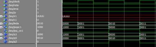
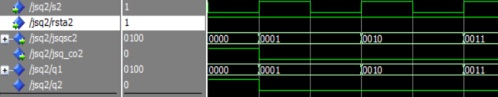
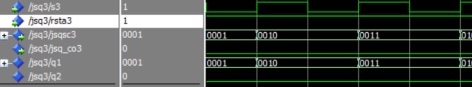
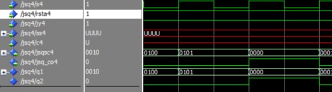
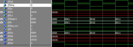
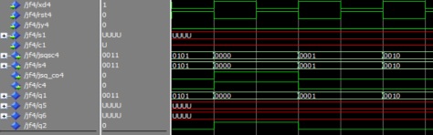
分频器程序:如附页。 仿真波形图: 图4.3.1b 4.3.2 功能选择器:通过key0来选择时钟电路的功能是计时还是校正,然后输出相应的值给计时器1,计数器(1-3)校正器,计数器4,计数器(4-6)校正器。 图4.3.2a 功能选择器模块 功能选择器程序:如附页。 波形仿真: 图4.3.2b 4.3.3 一输入二输出器即输入一个变量,输出两个和输入值相同的变量。 图4.3.3a 一输入二输出器模块 一输入二输出器的程序:如附页。 波形仿真图: 图4.3.3b 4.3.4 计数器1至计数器6 计数器1至计数器6都为计数的功能,前一个计数器进位,则后一个计数 器加1,计数器1至计数器6分别对应6个数码管。计数器5和计数器6两个为相互反馈作用,这样才可以为24进制。计数器1-2为秒,60进制;计数器3-4为分,60进制;计数器5-6为时,24进制。 计数器1模块 计数器2模块 计数器3模块 计数器4模块 计数器5模块 计数器6模块 图4.3.4a
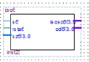
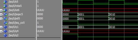
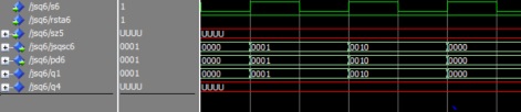
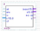
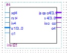
计数器1至计数器6程序:如附页。 波形仿真图: 计数器1 计数器2 计数器3 计数器4 计数器5 计数器6 图4.3.4a 4.3.5 计数器(1-3)的校正器、计数器(4-6)的校正器 计数器(1-3)的校正器是对计数器1的输出的值进行校正或更改后,再反馈给计数器1,同时将数值输出给后面的计数器,以达到修改计数器1到计数器3的值; 计数器(4-6)的校正器是对计数器4的输出的值进行校正或更改后,反馈给计数器四,同时将数值输出给后面的计数器,以达到修改计数器4到计数器6的值。 这两个校正器是否校正取决于功能控制器的选择。 计数器(1-3)的校正器 计数器(4-6)的校正器 图4.3.5a 程序代码:如附页。 仿真波形图: 计数器(1-3)的校正器 计数器(4-6)的校正器 图4.3.5b
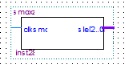
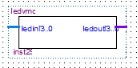
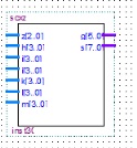
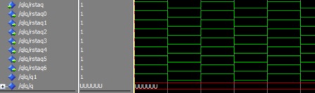
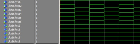
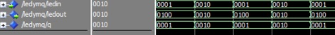
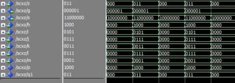
4.3.6防止异步清零器、异步清零器、数码管选择器、led灯选择器、数码管显示时间器①异步清零器:按key2时,即输入为低电平时,输出低电平给计数器1至 计数器6的清零端,然后可以对6个计数器的数值进行清零。 ②防止异步清零器:当前模式为校正模式,按key2来调整计数器4至计数 器6的数值时,防止计数器2至计数器6的数值被清零。 ③数码管选择器:用高频率来不断切换数码管显示,达到6个个数码管动态 显示的程度。 ④led灯选择器:每过一秒,在4个led灯之间切换循环显示亮,便于观察和检测程序。 ⑤数码管显示时间器:将6个计数器的值分别用6个数码管来显示,数码管扫描频率高的话,可以达到6个数码管一起亮的程度,即可以显示时间。
异步清零器 防止异步清零器 数码管选择器 led灯选择器 数码管显示时间器 图4.3.5a 各模块程序代码:如附页。 仿真波形: 异步清零器仿真波形 防止异步清零器仿真波形
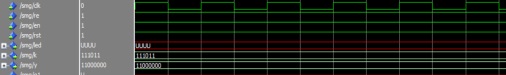
数码管选择器波形图 led灯选择器波形图 数码管显示时间器波形图 图4.3.6b 4.3.7顶层文件语句例化,将上述设计实体定义为元件,将这些元件与顶层的设计实体的各端口相连,实现自顶而下的层次化设计。
顶层文件程序:如附页。 仿真波形图(如图4.3.7):分频频率大,不易观察,但结果还是对的。 图4.3.7 4.4硬件配置调试
4.4.1硬件要求 (1)主芯片EP4CE6F17C8; (2)三个按键,按键key0,按键key1和按键key2; (3)ALINX开发板。
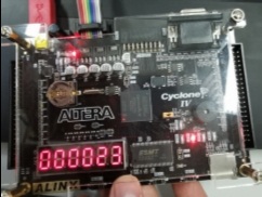
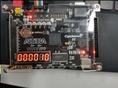
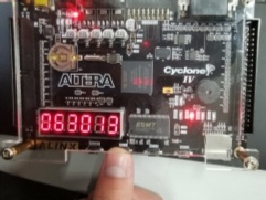
4.4.2引脚绑定图4.4.2 4.2.3现象说明将代码烧录进开发板后,按一次key0(按下后松开),数码管开始计时显示时间,时、分、秒依次为24进制、60进制、60进制。此时为时间计时模式,按下key1(按下后不放)时,暂停计时(如图1);按一次key2(按下后松开),6个数码管清零,即时钟的时、分、秒清零(如图2),然后开始计时,也可以作为秒表。 再按一次key0(按下后松开),此时模式变为校正模式(如图3),通过不断按key1(按下后松开),来对前三个数码管的数值进行更改(如图4),通过不断按key2(按下后松开),来对后三个数码管的数值进行更改(如图5)。即key1用来更改分的个位与秒的值,key2更改分的十位与时的值。以此达到对时钟时间的校正更改。 图1 暂停 图2 异步清零
图3 校正模式 图4 更改右边前三个数码管的值 图5 更改左边前三个数码管的值 5.实验总结5.1错误和解决方法 (1)按键在未消抖的情况下,对电子钟数值的校正不准确不精确,按一次键,相当于按过了几百次,时钟数值变化幅值太大了,几百几百的跳。 解决:对开发板的时钟源进行分频,分出一个对按键消抖的时钟信号,当检测到按下键了,经过时钟信号的上升沿时,才会输出按键的值,这样就会使一个时钟周期只会促发一次按键。以此来达到按键消抖。 (2)对计数器1进行校正或者计数时,都要出发不同的时钟信号上升沿,但一个进程不允许检测多个信号的上升沿。 解决:再建立一个校正模块(即计数器1-3的校正器),对计数器1的输出值判断是否要校正,若要校正,那么校正完毕后,再将数值反馈给计数器1,使计数器1的输入值变为校正过后的值,同时将数值输出给下一个模块。若无校正,则无须反馈,直接将数值输出到下一模块。计数器4也依此方法。以此来达到对电子钟的时间进行校正更改。 (3)key2有两个功能,计时模式时为清零键,校正模式为对电子钟的时间进行更改,按下时,经常两个功能都触发,使得每次校正后的值都被清零。 解决:建立一个模块(防止异步清零模块),对电子钟此时的功能判断,使key有不同的功能,就不会使key2的两种功能同时触发了。
(4)电子中的时的个位(第五个数码管)和十位(第六个数码管),其个位是9进制的,十位是2进制的,但其电子钟的时是24进制的。 解决:从十位(第六个数码管)引出一个反馈给个位(第五个数码管),当十位为2时,个位为4进制。这样就使得电子钟的时为24进制了,也不会使个位(第五个数码管)和十位(第六个数码管)的进制与电子钟的时的进制发生冲突了。 5.2心得与体会 这次期末时间有限,使得这次设计设计电子钟的时间太少,解决程序代码的时间太少了,未能更进一步对设计出来的电子钟进行功能的的增加,如闹钟,整点报时等功能,有点遗憾。但也学到了许多东西,对开发FPGA的VHDL语言掌握更得更好了,解决问题也有了一定的方法和耐心了,在设计学习的过程中更能静下心来了。这此设计时间虽短,但对我的意义很大。我也记住了,单片机的按键要消抖,那么PFGA的按键也要消抖,无论哪种,对按键都要消抖。按键在哪都要消抖,不然对其系统模块会产生很大的错误。
附页:
代码按目录依次为
分频器:
library ieee;
use ieee.std_logic_1164.all;
use ieee.std_logic_unsigned.all;
use ieee.std_logic_arith.all;
entity fpq is
port (clkf:in std_logic;
clk_1hz,clk_smg,clk_xd,clk_xd4,clk_k:out std_logic);
end fpq;
architecture fpq of fpq is
signal q1:integer range 0 to 49999999;
signal q2:integer range 0 to 49999;
signal q3:integer range 0 to 16999999;
begin
process(clkf) begin
if rising_edge(clkf) then
if q1=4999999 then q1<=0;else
q1<=q1+1;end if;
if q1>2499999 then clk_1hz<='0';else
clk_1hz<='1';
end if;
if q2=49999 then q2<=0;else
q2<=q2+1;end if;
if q2>24999 then clk_smg<='0';else
clk_smg<='1';
end if;
if q3=16999999 then q3<=0;else
q3<=q3+1;end if;
if q3>9499999 then clk_xd<='0';clk_xd4<='0';clk_k<='0';else
clk_xd<='1';clk_xd4<='1';clk_k<='1';
end if;
end if;
end process ;
end fpq;
功能选择器:
library ieee;
use ieee.std_logic_1164.all;
use ieee.std_logic_unsigned.all;
entity kzq is
port (ret,clkk:in std_logic;
jy1,j1,jy2,j2,j56:out std_logic);
end kzq;
architecture kzq of kzq is
signal q0,q1,q2,q3,qclk:std_logic;
signal qx:std_logic_vector(1 downto 0);
begin
process(ret) begin
q0<=ret;
if q0='0' then
if falling_edge(clkk) then
if qx<1 then qx<=qx+1;else
qx<=(others=>'0');end if;end if;end if;
case qx is
when "00"=>jy1<='0';j1<='0';jy2<='0';j2<='0';j56<='0';
when "01"=>jy1<='1';j1<='1';jy2<='1';j2<='1';j56<='1';
when others=>null;
end case;
end process;
end kzq;
一输入二输出器:
library ieee;
use ieee.std_logic_1164.all;
use ieee.std_logic_unsigned.all;
entity enx is
port (ena:in std_logic;
e1,e2:out std_logic);
end enx;
architecture enx of enx is
begin
e1<=ena;
e2<=ena;
end enx;
计数器1:
library ieee;
use ieee.std_logic_1164.all;
use ieee.std_logic_unsigned.all;
entity jsq is
port (clock,rsta,ena,jy:in std_logic;
s1:in std_logic_vector(3 downto 0);
c1:in std_logic;
leda:out std_logic_vector(3 downto 0);
jsqsc1:out std_logic_vector(3 downto 0);
jsq_co1:out std_logic);
end jsq;
architecture jsq1 of jsq is
signal q1,q5:std_logic_vector(3 downto 0);
signal q2:std_logic;
begin
process(clock)
variable q3,q4:std_logic_vector(3 downto 0);
begin
case jy is
when '1' =>
if rsta='0' then q3:=(others=>'0');
elsif rising_edge(clock) then
if ena='0' then q1<=q1;q5<=q5; else
if q3<9 then q3:=q3+1;q2<='0';
else q3:=(others=>'0');q2<='1';end if;
if q4<3 then q4:=q4+1;
else q4:=(others=>'0');end if;end if;end if;
q1<=q3;q5<=q4;
when '0' => q1<=s1;q2<=c1;
when others =>null;
end case;
end process;
leda<=q5;jsqsc1<=q1;jsq_co1<=q2;
end jsq1;
计数器2:
library ieee;
use ieee.std_logic_1164.all;
use ieee.std_logic_unsigned.all;
entity jsq2 is
port (s2,rsta2:in std_logic;
jsqsc2:out std_logic_vector(3 downto 0);
jsq_co2:out std_logic);
end jsq2;
architecture jsq2 of jsq2 is
signal q1:std_logic_vector(3 downto 0);
signal q2:std_logic;
begin
process(s2)
variable q3:std_logic_vector(3 downto 0);
begin
if rsta2='0' then q3:=(others=>'0');q1<="0000";
elsif rising_edge(s2) then
if q3<5 then q3:=q3+1;q2<='0';
else q3:=(others=>'0');q2<='1';
end if;end if;
q1<=q3;
end process;
jsq_co2<=q2;
jsqsc2<=q1;
end jsq2;
计数器3:
library ieee;
use ieee.std_logic_1164.all;
use ieee.std_logic_unsigned.all;
entity jsq3 is
port (s3,rsta3:in std_logic;
jsqsc3:out std_logic_vector(3 downto 0);
jsq_co3:out std_logic);
end jsq3;
architecture jsq3 of jsq3 is
signal q1:std_logic_vector(3 downto 0);
signal q2:std_logic;
begin
process(s3)
variable q3:std_logic_vector(3 downto 0);
begin
if rsta3='0' then q3:=(others=>'0');q1<="0000";
elsif rising_edge(s3) then
if q3<9 then q3:=q3+1;q2<='0';
else q3:=(others=>'0');q2<='1';
end if;end if;
q1<=q3;
end process;
jsq_co3<=q2;
jsqsc3<=q1;
end jsq3;
计数器4:
library ieee;
use ieee.std_logic_1164.all;
use ieee.std_logic_unsigned.all;
entity jsq4 is
port (s4,rsta4,jy4:in std_logic;
ss4:in std_logic_vector(3 downto 0);
c4:in std_logic;
jsqsc4:out std_logic_vector(3 downto 0);
jsq_co4:out std_logic);
end jsq4;
architecture jsq4 of jsq4 is
signal q1:std_logic_vector(3 downto 0);
signal q2:std_logic;
begin
process(s4,rsta4,jy4,ss4,c4)
--variable q3:std_logic_vector(3 downto 0);
begin
case jy4 is
when '1'=>
if rsta4='0' then q1<="0000";
elsif rising_edge(s4) then
if q1<5 then q1<=q1+1;q2<='0';
else q1<=(others=>'0');q2<='1';end if;end if;
--q1<=q3;
when'0'=>
q1<=ss4;q2<=c4;
when others=>null;
end case;
--q1<=q3;
end process;
jsqsc4<=q1;
jsq_co4<=q2;
end jsq4;
计数器5:
library ieee;
use ieee.std_logic_1164.all;
use ieee.std_logic_unsigned.all;
entity jsq5 is
port (s5,rsta5:in std_logic;
sz6:in std_logic_vector(3 downto 0);
jsqsc5:out std_logic_vector(3 downto 0);
pd5:out std_logic_vector(3 downto 0);
jsq_co5:out std_logic);
end jsq5;
architecture jsq5 of jsq5 is
signal q1,q4:std_logic_vector(3 downto 0);
signal q2:std_logic;
begin
process(s5)
variable q3:std_logic_vector(3 downto 0);
begin
q4<=sz6;
if rising_edge(s5) then
if q3<9 then q3:=q3+1;q2<='0';
else q3:=(others=>'0');q2<='1';
end if;
if ((q1=3) and (q4=2)) then q3:=(others=>'0');q2<='0';end if;end if;
if rsta5='0' then q3:=(others=>'0');q1<="0000";end if;
q1<=q3;
end process;
jsq_co5<=q2;
jsqsc5<=q1;
pd5<=q1;
end jsq5;
计数器6:
library ieee;
use ieee.std_logic_1164.all;
use ieee.std_logic_unsigned.all;
entity jsq6 is
port (s6,rsta6:in std_logic;
sz5:in std_logic_vector(3 downto 0);
jsqsc6:out std_logic_vector(3 downto 0);
pd6:out std_logic_vector(3 downto 0)
);
end jsq6;
architecture jsq6 of jsq6 is
signal q1,q4:std_logic_vector(3 downto 0);
begin
process(s6,sz5)
variable q3:std_logic_vector(3 downto 0);
begin
if rising_edge(s6) then
if q3<2 then q3:=q3+1;
else q3:=(others=>'0');
end if;
if ((q1=3) and (q4=2)) then q3:=(others=>'0');end if;end if;
if rsta6='0' then q3:=(others=>'0');q1<="0000";end if;
q1<=q3;
end process;
jsqsc6<=q1;
pd6<=q1;
end jsq6;
计数器(1-3)的校正器:
library ieee;
use ieee.std_logic_1164.all;
use ieee.std_logic_unsigned.all;
entity jf is
port (xd,ena,jy:in std_logic;
s1:in std_logic_vector(3 downto 0);
c1:in std_logic;
jsqsc1,s:out std_logic_vector(3 downto 0);
jsq_co1,c:out std_logic);
end jf;
architecture jf of jf is
signal q1,q5,q6:std_logic_vector(3 downto 0);
signal q2:std_logic;
begin
process(xd)
variable q3:std_logic_vector(3 downto 0);
begin
case jy is
when '0'=>
if ena='0' then
if rising_edge(xd) then
if q3<9 then q3:=q3+1;q2<='0';
else q3:=(others=>'0');q2<='1';end if;end if;end if;
q1<=q3;
when '1'=>
q1<=s1;q2<=c1;
when others =>null;
end case;
end process;
jsqsc1<=q1;jsq_co1<=q2;
s<=q1;c<=q2;
end jf;
计数器(4-6)的校正器:
library ieee;
use ieee.std_logic_1164.all;
use ieee.std_logic_unsigned.all;
entity jf4 is
port (xd4,rst4,jy4:in std_logic;
s1:in std_logic_vector(3 downto 0);
c1:in std_logic;
jsqsc4,s4:out std_logic_vector(3 downto 0);
jsq_co4,c4:out std_logic);
end jf4;
architecture jf4 of jf4 is
signal q1,q5,q6:std_logic_vector(3 downto 0);
signal q2:std_logic;
begin
process(xd4)
--variable q3:std_logic_vector(3 downto 0);
begin
case jy4 is
when '0'=>
if rst4='0' then
if rising_edge(xd4) then
if q1<5 then q1<=q1+1;q2<='0';
else q1<=(others=>'0');q2<='1';end if;end if;end if;
--q1<=q3;
when '1'=>
q1<=s1;q2<=c1;
when others =>null;
end case;
end process;
jsqsc4<=q1;jsq_co4<=q2;
s4<=q1;c4<=q2;
end jf4;
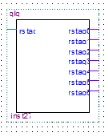
异步清零器:
library ieee;
use ieee.std_logic_1164.all;
use ieee.std_logic_unsigned.all;
entity qlq is
port (rstaq:in std_logic;
rstaq0,rstaq1,rstaq2,rstaq3,rstaq4,rstaq5,rstaq6:out std_logic);
end qlq;
architecture qlq of qlq is
signal q1:std_logic;
signal q:std_logic_vector(5 downto 0);
begin
q1<=rstaq;
rstaq0<=q1;
rstaq1<=q1;
rstaq2<=q1;
rstaq3<=q1;
rstaq4<=q1;
rstaq5<=q1;
rstaq6<=q1;
end qlq;
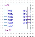
防止异步清零器:
library ieee;
use ieee.std_logic_1164.all;
use ieee.std_logic_unsigned.all;
use ieee.std_logic_arith.all;
entity kz56 is
port(jy56,rsta2,rsta3,rsta4,rsta5,rsta6:in std_logic;
rst2,rst3,rst4,rst5,rst6:out std_logic);
end kz56;
architecture kz56 of kz56 is
begin
process(jy56) begin
if jy56='0' then rst2<='1';rst3<='1';rst4<='1';rst5<='1';rst6<='1';else
rst2<=rsta2;rst3<=rsta3;rst4<=rsta4;rst5<=rsta5;rst6<=rsta6;
end if;
end process;
end kz56;
数码管选择器:
library ieee;
use ieee.std_logic_1164.all;
use ieee.std_logic_unsigned.all;
entity smgxz is
port (clksmg:in std_logic;
sle:out std_logic_vector(2 downto 0));
end smgxz;
architecture smgxz of smgxz is
signal q1:std_logic_vector(2 downto 0);
begin
process(clksmg)
variable asmg:std_logic_vector(2 downto 0); begin
if rising_edge(clksmg) then
if asmg<5 then asmg:=asmg+1;else
asmg:="000";
end if;end if;
q1<=asmg;
sle<=q1;
end process;
end smgxz;
led灯选择器:
library ieee;
use ieee.std_logic_1164.all;
use ieee.std_logic_unsigned.all;
entity ledymq is
port (ledin:in std_logic_vector(3 downto 0);
ledout:out std_logic_vector(3 downto 0));
end ledymq;
architecture ledymq of ledymq is
signal q:std_logic_vector(3 downto 0);
begin
process(ledin) begin
q<=ledin;
case q is
when "0000" => ledout<="0001";
when "0001" => ledout<="0010";
when "0010" => ledout<="0100";
when "0011" => ledout<="1000";
when others=>null;
end case;
end process;
end ledymq;
数码管显示时间器:
library ieee;
use ieee.std_logic_1164.all;
use ieee.std_logic_unsigned.all;
entity scxz is
port( z:in std_logic_vector(2 downto 0);
g:out std_logic_vector(5 downto 0);
s:out std_logic_vector(7 downto 0);
h,i,j,k,l,m:in std_logic_vector(3 downto 0));
end scxz;
architecture scxz of scxz is
signal p:std_logic_vector(3 downto 0);
signal q1:std_logic_vector(2 downto 0);
begin
process(z,h,i,j) begin
q1<=z;
if q1="000" then p<=h; g<="111110";
elsif q1="001" then p<=i; g<="111101";
elsif q1="010" then p<=j; g<="111011";
elsif q1="011" then p<=k; g<="110111";
elsif q1="100" then p<=l; g<="101111";
elsif q1="101" then p<=m; g<="011111";
end if;
case p is
when "0000"=>s<="11000000";--0
when "0001"=>s<="11111001";--1
when "0010"=>s<="10100100";--2
when "0011"=>s<="10110000";--3
when "0100"=>s<="10011001";--4
when "0101"=>s<="10010010";--5
when "0110"=>s<="10000010";--6
when "0111"=>s<="11111000";--7
when "1000"=>s<="10000000";--8
when "1001"=>s<="10010000";--9
when others=>s<="11000000";--0
end case;
end process;
end scxz;

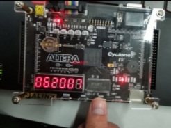
制作出来的实物图如下:
代码下载:
 代码与文档.7z
(5.33 MB, 下载次数: 30)
代码与文档.7z
(5.33 MB, 下载次数: 30)
| 


 QQ好友和群
 QQ空间
QQ空间 腾讯微博
腾讯微博 腾讯朋友
腾讯朋友 收藏
收藏 淘帖
淘帖 顶
顶 踩
踩

