与GPIO相关的寄存器
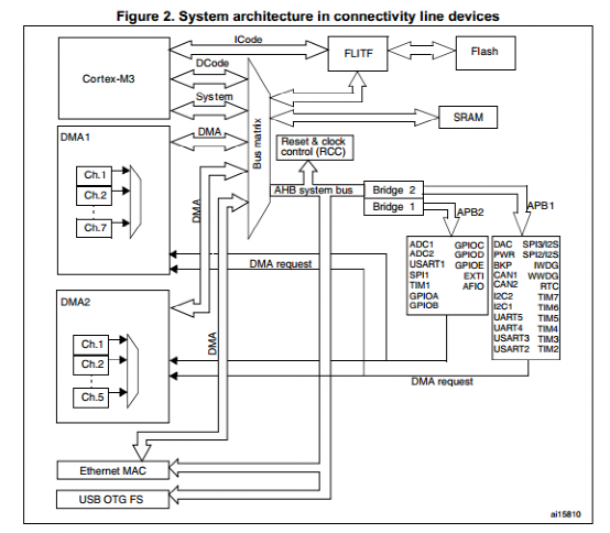
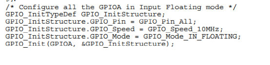
STM32F10x处理器公有7个IO端口:A、B、C、D、E、F、G,每个端口上有16个引脚。 每个IO端口都有2个32位的配置寄存器,2个32位的数据寄存器(input output),一个32位的置位/复位寄存器,一个16位的复位寄存器,一个32位的锁定寄存器。 具体有: 端口配置寄存器低位 GPIO_CRL 端口配置寄存器高位 GPIO_CRH 端口输入数据寄存器 GPIO_IDR 端口输出数据寄存器 GPIO_ODR 端口位置位/复位寄存器 GPIO_BSRR 端口位复位寄存器 GPIO_BRR 端口配置锁定寄存器 GPIO_LCKR 事件控制寄存器 EVCR 复用重映射和调试I/O配置寄存器 MAPR 外部中断线路0-15配置寄存器 EXTICR 这些寄存器在系统头文件stm32f10x.h的定义如下: typedef struct { __IO uint32_t CRL; __IO uint32_t CRH; __IO uint32_t IDR; __IO uint32_t ODR; __IO uint32_t BSRR; __IO uint32_t BRR; __IO uint32_t LCKR; } GPIO_TypeDef; /** * @brief Alternate Function I/O */ typedef struct { __IO uint32_t EVCR; __IO uint32_t MAPR; __IO uint32_t EXTICR[4]; uint32_t RESERVED0; __IO uint32_t MAPR2; } AFIO_TypeDef; /** 端口引脚的设置 l引脚原理图 l可以设置的状态 l不同状态相关寄存器的设置值 l程序设计时不同状态引用的宏定义 函数 与GPIO相关的函数:在stm32f10x_gpio.h中进行了声明 1.void GPIO_DeInit(GPIO_TypeDef* GPIOx);//IO缺省值初始化函数 2.void GPIO_AFIODeInit(void);//初始化复用功能寄存器为初始化值 3.void GPIO_Init(GPIO_TypeDef* GPIOx, GPIO_InitTypeDef* GPIO_InitStruct);//使用GPIO_InitStruct中的参数对IO口进行初始化 4.void GPIO_StructInit(GPIO_InitTypeDef* GPIO_InitStruct);把GPIO_InitStruct中的每个参数按缺省值填入 5.uint8_t GPIO_ReadInputDataBit(GPIO_TypeDef* GPIOx, uint16_t GPIO_Pin);读取指定端口引脚的输入 6.uint16_t GPIO_ReadInputData(GPIO_TypeDef* GPIOx);读取指定端口的输入 7.uint8_t GPIO_ReadOutputDataBit(GPIO_TypeDef* GPIOx, uint16_t GPIO_Pin);读取指定端口引脚的输出 8.uint16_t GPIO_ReadOutputData(GPIO_TypeDef* GPIOx);读取指定端口的输出 9.void GPIO_SetBits(GPIO_TypeDef* GPIOx, uint16_t GPIO_Pin);设置指定端口引脚的位 10.void GPIO_ResetBits(GPIO_TypeDef* GPIOx, uint16_t GPIO_Pin);清除指定端口引脚的位 11.void GPIO_WriteBit(GPIO_TypeDef* GPIOx, uint16_t GPIO_Pin, BitAction BitVal);设置或清除指定的数据端口为 12.void GPIO_Write(GPIO_TypeDef* GPIOx, uint16_t PortVal);向指定的端口写入数据 13.void GPIO_PinLockConfig(GPIO_TypeDef* GPIOx, uint16_t GPIO_Pin);锁定端口引脚的设置寄存器 14.void GPIO_EventOutputConfig(uint8_t GPIO_PortSource, uint8_t GPIO_PinSource);//选择端口引脚作为事件输出 15.void GPIO_EventOutputCmd(FunctionalState NewState);使能 或失能事件输出 16.void GPIO_PinRemapConfig(uint32_t GPIO_Remap, FunctionalState NewState);改变指定管脚的地址映射 17.void GPIO_EXTILineConfig(uint8_t GPIO_PortSource, uint8_t GPIO_PinSource);选择端口引脚用作外部中断线路 18.void GPIO_ETH_MediaInterfaceConfig(uint32_t GPIO_ETH_MediaInterface);选择以太网的接口 外设初始化和设置操作过程 1、在主应用文件中,声明一个PPP_InitTypeDef结构体类型 ,如PPP_InitTypeDef PPP_InitStructure; 这个PPP_InitTypeDef结构体已经在PPP对应的头文件中进行了定义。 可以看到这个结构体中有3个元素。管脚、端口速度、端口模式 2、为变量PPP_InitStructure的各个结构成员填入允许的值。 采用两种方式: PPP_InitStructure.member1=val1; PPP_InitStructure.member2=val2; PPP_InitStructure.memberN=valN; 以上步骤可以合并在同一行里,用于优化代码大小: PPP_InitTypeDef PPP_InitStructure={val1,val2,……valN} 仅设置结构体中的部分成员:这种情况下,用户应当首先调用函数PPP_SturcInit( )来初始化变量PPP_InitStructure,然后再修改其中需要修改的成员。这样可以保证其他成员(多为缺省值)被正确填入。 PPP_StructInit (&PPP_InitStructure); PPP_InitStructure.memberX=valX; PPP_InitStructure.memberY=valY; 3、调用函数PPP_Init( )来初始化外设PPP。 4、在这一步,外设PPP已被初始化。可以调用函数PPP_Cmd( )来使能之。 PPP_Cmd(PPP,ENABLE); 注意: 1、在设置一个外设之前,必须调用以下一个函数来使能它的时钟: RCC_AHBPeriphClockCmd(RCC_AHBPeriph_PPPx,ENABLE); RCC_APB2PeriphClockCmd(RCC_APB2Periph_PPPx,ENABLE); RCC_APB1PeriphClockCmd(RCC_APB1Periph_PPPx,ENABLE); 具体应该调用那个函数看下图 2、可以调用函数PPP_DeInit(PPP)来把外设PPP的所用寄存器复位为缺省值 3、在外设设置完成后,继续修改它的一些参数,可以参照如下步骤: PPP_InitStructure.memberX=valx; PPP_InitStructure.memberY=valy; PPP_Init(PPP,&PPP_InitStructure); 总结 如何将GPIOA设置成浮动输入模式 下面看一个实际的例子。 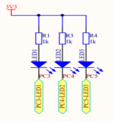 循环点亮如图的三个发光二极管。 在模板的文件中新建一个文件夹led. 在MDK中新建led.h和led.c文件 Led.c文件内容如下: #include"led.h" /* 函数名:LED_GPIO_Config 描述: 配置LED用到的I/O口 输入 : 无 输出: 无 */
void LED_GPIO_Config(void) { GPIO_InitTypeDef GPIO_InitStructure;//定义一个GPIO_InitTypeDef类型的结构体 GPIO_InitStructure.GPIO_Pin=GPIO_Pin_3|GPIO_Pin_4|GPIO_Pin_5; //选择要控制的引脚 GPIO_InitStructure.GPIO_Mode=GPIO_Mode_Out_PP;//设置引脚模式为通用推挽输出 GPIO_InitStructure.GPIO_Speed=GPIO_Speed_50MHz;//设置引脚速率为50MHz GPIO_Init(GPIOC,&GPIO_InitStructure);//调用库函数初始化GPIOC RCC_APB2PeriphClockCmd( RCC_APB2Periph_GPIOC, ENABLE); //开启GPIOC的外设时钟 GPIO_SetBits(GPIOC,GPIO_Pin_3|GPIO_Pin_4|GPIO_Pin_5);//关闭所有的led } Led.h文件如下: #ifndef __LED_H #define __LED_H #include"stm32f10x.h"
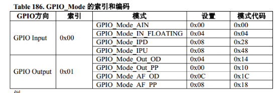
#define ON 0 #define OFF 1 #define LED1(a) if(a) GPIO_SetBits(GPIOC,GPIO_Pin_3);\ else GPIO_ResetBits(GPIOC,GPIO_Pin_3)//调用置位和复位函数函数 #define LED2(a) if(a)GPIO_SetBits(GPIOC,GPIO_Pin_4);\ else GPIO_ResetBits(GPIOC,GPIO_Pin_4) #define LED3(a) if(a) GPIO_SetBits(GPIOC,GPIO_Pin_5);\ else GPIO_ResetBits(GPIOC,GPIO_Pin_5) /*也可以调用void GPIO_Write(GPIO_TypeDef* GPIOx, uint16_t PortVal);向指定的端口写入数据 #define LED1(a) if(a) GPIO_Write(GPIOC,0xfffb );\ else GPIO_Write(GPIOC,0xffff ) #define LED2(a) if(a) GPIO_Write(GPIOC,0xfff7 );\ else GPIO_Write(GPIOC,0xffff ) #define LED3(a) if(a) GPIO_Write(GPIOC,0xffef );\ else GPIO_Write(GPIOC,0xffff ) */ void LED_GPIO_Config(void); #endif 在main.c文件中输入如下代码: #include "stm32f10x.h" #include "led.h" void Delay(vu32 nCount); int main(void) { LED_GPIO_Config();// while(1) { LED1(ON); Delay(0x0fffef); LED1(OFF); LED2(ON); Delay(0x0fffef); LED2(OFF); LED3(ON); Delay(0x0fffef); LED3(OFF); } } void Delay(vu32 nCount) { for(;nCount!=0;nCount--); } 打开stm32f10x_conf.h文件,将不需要的头文件注释掉 /* Includes ------------------------------------------------------------------*/ /* Uncomment/Comment the line below to enable/disable peripheral header file inclusion */ //#include "stm32f10x_adc.h" //#include "stm32f10x_bkp.h" //#include "stm32f10x_can.h" //#include "stm32f10x_cec.h" //#include "stm32f10x_crc.h" //#include "stm32f10x_dac.h" //#include "stm32f10x_dbgmcu.h" //#include "stm32f10x_dma.h" //#include "stm32f10x_exti.h" //#include "stm32f10x_flash.h" //#include "stm32f10x_fsmc.h" #include "stm32f10x_gpio.h" //#include "stm32f10x_i2c.h" ///#include "stm32f10x_iwdg.h" //#include "stm32f10x_pwr.h" #include "stm32f10x_rcc.h" //#include "stm32f10x_rtc.h" //#include "stm32f10x_sdio.h" //#include "stm32f10x_spi.h" //#include "stm32f10x_tim.h" //#include "stm32f10x_usart.h" //#include "stm32f10x_wwdg.h" //#include "misc.h" /* High level functions for NVIC and SysTick (add-on to CMSIS functions) */ “编译”----“debug” 运行结果如下图 具体的代码分析如下: 在led.c文件中定义了一个函数, void LED_GPIO_Config(void).作用是对端口进行初始化。 初始化设置的步骤,就像前面说明的那样。 1、GPIO_InitTypeDef GPIO_InitStructure;//定义一个GPIO_InitTypeDef类型的结构体 对于GPIO_InitTypeDef这个结构体在stm32f10x_gpio.h头文件中做了如下定义 typedef struct { uint16_t GPIO_Pin; /*!< Specifies the GPIO pins to be configured. This parameter can be any value of @ref GPIO_pins_define */ GPIOSpeed_TypeDef GPIO_Speed; /*!< Specifies the speed for the selected pins. This parameter can be a value of @ref GPIOSpeed_TypeDef */ GPIOMode_TypeDef GPIO_Mode; /*!< Specifies the operating mode for the selected pins. This parameter can be a value of @ref GPIOMode_TypeDef */ }GPIO_InitTypeDef; 包含3个不同类型的成员,引脚、速度、模式。 2、然后是对这3个成员赋值 GPIO_InitStructure.GPIO_Pin=GPIO_Pin_3|GPIO_Pin_4|GPIO_Pin_5; //选择要控制的引脚 GPIO_InitStructure.GPIO_Mode=GPIO_Mode_Out_PP;//设置引脚模式为通用推挽输出 GPIO_InitStructure.GPIO_Speed=GPIO_Speed_50MHz;//设置引脚速率为50MHz 其中引脚的选项在stm32f10x_gpio.h中是如下定义的, /** @defgroup GPIO_pins_define * @{ */ #define GPIO_Pin_0 ((uint16_t)0x0001) /*!< Pin 0 selected */ #define GPIO_Pin_1 ((uint16_t)0x0002) /*!< Pin 1 selected */ #define GPIO_Pin_2 ((uint16_t)0x0004) /*!< Pin 2 selected */ #define GPIO_Pin_3 ((uint16_t)0x0008) /*!< Pin 3 selected */ #define GPIO_Pin_4 ((uint16_t)0x0010) /*!< Pin 4 selected */ #define GPIO_Pin_5 ((uint16_t)0x0020) /*!< Pin 5 selected */ #define GPIO_Pin_6 ((uint16_t)0x0040) /*!< Pin 6 selected */ #define GPIO_Pin_7 ((uint16_t)0x0080) /*!< Pin 7 selected */ #define GPIO_Pin_8 ((uint16_t)0x0100) /*!< Pin 8 selected */ #define GPIO_Pin_9 ((uint16_t)0x0200) /*!< Pin 9 selected */ #define GPIO_Pin_10 ((uint16_t)0x0400) /*!< Pin 10 selected */ #define GPIO_Pin_11 ((uint16_t)0x0800) /*!< Pin 11 selected */ #define GPIO_Pin_12 ((uint16_t)0x1000) /*!< Pin 12 selected */ #define GPIO_Pin_13 ((uint16_t)0x2000) /*!< Pin 13 selected */ #define GPIO_Pin_14 ((uint16_t)0x4000) /*!< Pin 14 selected */ #define GPIO_Pin_15 ((uint16_t)0x8000) /*!< Pin 15 selected */ #define GPIO_Pin_All ((uint16_t)0xFFFF) /*!< All pins selected */ 模式在stm32f10x_gpio.h头文件中是如下定义的, /** * @brief Configuration Mode enumeration */ typedef enum //枚举 { GPIO_Mode_AIN = 0x0, GPIO_Mode_IN_FLOATING = 0x04, GPIO_Mode_IPD = 0x28, GPIO_Mode_IPU = 0x48, GPIO_Mode_Out_OD = 0x14, GPIO_Mode_Out_PP = 0x10, GPIO_Mode_AF_OD = 0x1C, GPIO_Mode_AF_PP = 0x18 }GPIOMode_TypeDef; 速度在stm32f10x_gpio.h头文件中是如下定义的, /** * @brief Output Maximum frequency selection */ typedef enum { GPIO_Speed_10MHz = 1, GPIO_Speed_2MHz, GPIO_Speed_50MHz }GPIOSpeed_TypeDef; 3、GPIO_Init(GPIOC,&GPIO_InitStructure);//调用库函数初始化GPIOC 这个函数在stm32f10x_gpio.c文件中是如下定义的, /** * @brief Initializes the GPIOx peripheral according to the specified * parameters in the GPIO_InitStruct. * @param GPIOx: where x can be (A..G) to select the GPIO peripheral. * @param GPIO_InitStruct: pointer to a GPIO_InitTypeDef structure that * contains the configuration information for the specified GPIO peripheral. * @retval None */ void GPIO_Init(GPIO_TypeDef* GPIOx, GPIO_InitTypeDef* GPIO_InitStruct) { uint32_t currentmode = 0x00, currentpin = 0x00, pinpos = 0x00, pos = 0x00; uint32_t tmpreg = 0x00, pinmask = 0x00; /* Check the parameters */ assert_param(IS_GPIO_ALL_PERIPH(GPIOx)); assert_param(IS_GPIO_MODE(GPIO_InitStruct->GPIO_Mode)); assert_param(IS_GPIO_PIN(GPIO_InitStruct->GPIO_Pin)); /*---------------------------- GPIO Mode Configuration -----------------------*/ currentmode = ((uint32_t)GPIO_InitStruct->GPIO_Mode) & ((uint32_t)0x0F);//只取低4位 if ((((uint32_t)GPIO_InitStruct->GPIO_Mode) & ((uint32_t)0x10)) != 0x00)//为输出模式 { /* Check the parameters */ assert_param(IS_GPIO_SPEED(GPIO_InitStruct->GPIO_Speed));//检查输出的参数是否正确 /* Output mode */ currentmode |= (uint32_t)GPIO_InitStruct->GPIO_Speed; } /*---------------------------- GPIO CRL Configuration ------------------------*/ /* Configure the eight low port pins */ if (((uint32_t)GPIO_InitStruct->GPIO_Pin & ((uint32_t)0x00FF)) != 0x00)//如果是输入模式 { tmpreg = GPIOx->CRL; for (pinpos = 0x00; pinpos < 0x08; pinpos++) { pos = ((uint32_t)0x01) << pinpos; /* Get the port pins position */ currentpin = (GPIO_InitStruct->GPIO_Pin) & pos; if (currentpin == pos) { pos = pinpos << 2; /* Clear the corresponding low control register bits */ pinmask = ((uint32_t)0x0F) << pos; tmpreg &= ~pinmask; /* Write the mode configuration in the corresponding bits */ tmpreg |= (currentmode << pos); /* Reset the corresponding ODR bit */ if (GPIO_InitStruct->GPIO_Mode == GPIO_Mode_IPD) { GPIOx->BRR = (((uint32_t)0x01) << pinpos); } else { /* Set the corresponding ODR bit */ if (GPIO_InitStruct->GPIO_Mode == GPIO_Mode_IPU) { GPIOx->BSRR = (((uint32_t)0x01) << pinpos); } } } } GPIOx->CRL = tmpreg; } /*---------------------------- GPIO CRH Configuration ------------------------*/ /* Configure the eight high port pins */ if (GPIO_InitStruct->GPIO_Pin > 0x00FF) { tmpreg = GPIOx->CRH; for (pinpos = 0x00; pinpos < 0x08; pinpos++) { pos = (((uint32_t)0x01) << (pinpos + 0x08)); /* Get the port pins position */ currentpin = ((GPIO_InitStruct->GPIO_Pin) & pos); if (currentpin == pos) { pos = pinpos << 2; /* Clear the corresponding high control register bits */ pinmask = ((uint32_t)0x0F) << pos; tmpreg &= ~pinmask; /* Write the mode configuration in the corresponding bits */ tmpreg |= (currentmode << pos); /* Reset the corresponding ODR bit */ if (GPIO_InitStruct->GPIO_Mode == GPIO_Mode_IPD) { GPIOx->BRR = (((uint32_t)0x01) << (pinpos + 0x08)); } /* Set the corresponding ODR bit */ if (GPIO_InitStruct->GPIO_Mode == GPIO_Mode_IPU) { GPIOx->BSRR = (((uint32_t)0x01) << (pinpos + 0x08)); } } } GPIOx->CRH = tmpreg; } } GPIO_Init(GPIOC,&GPIO_InitStructure);//调用库函数初始化GPIOC函数中的 GPIO_InitStructure是我们自己定义的一个结构体变量名 GPIO_InitTypeDef GPIO_InitStructure;//定义一个GPIO_InitTypeDef类型的结构体变量 后记: 熟悉了GPIO的应用,对如何查找固件库和参考手册中的相关内容、系统头文件及外设的.H和.C文件构成、函数的功能及调用,就有了一定的了解。举一反三对于其他的外设基本数据的架构及应用与GPIO类似。至于.S的启动文件的分析以后再做说明。
| 


 QQ好友和群
 QQ空间
QQ空间 腾讯微博
腾讯微博 腾讯朋友
腾讯朋友 收藏
收藏 淘帖
淘帖 顶
顶 踩
踩

