
由于串行多位加法器的高位相加时要等待低位的进位,所以速度受到进位信号的限制而变慢,人们又设计了一种多位数超前进位加法器逻辑电路,使每位求和结果直接接受加数和被加数而不必等待地位进位,而与低位的进位信号无关,这就大大的提高了运算速度。现在简单介绍超前进位的运算方法,以及VHDL可编程逻辑编程。
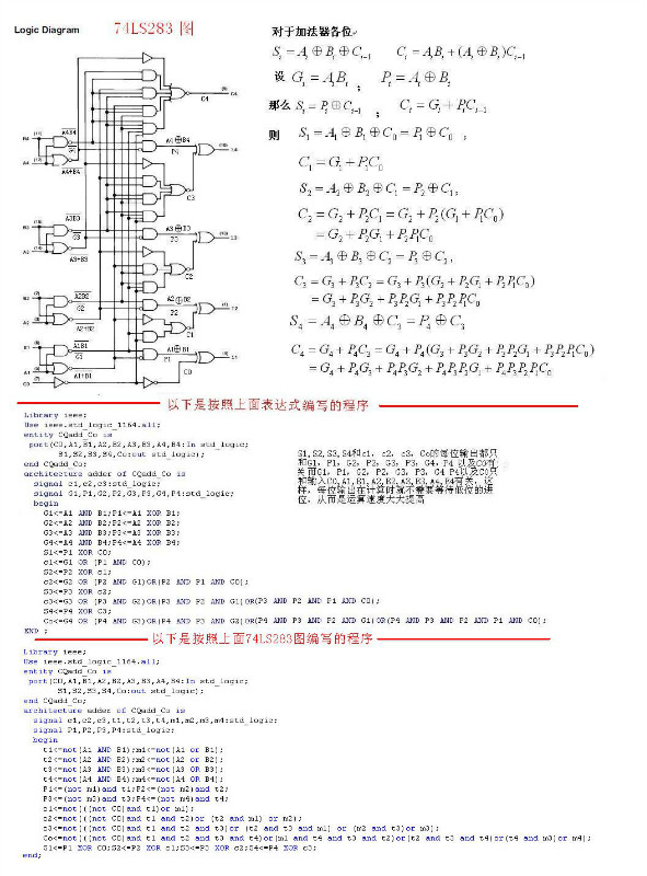
Library ieee;
Use ieee.std_logic_1164.all;
entity CQadd_Co is
port(C0,A1,B1,A2,B2,A3,B3,A4,B4:In std_logic;
S1,S2,S3,S4,Co:out std_logic);
end CQadd_Co;
architecture adder of CQadd_Co is
signal c1,c2,c3,t1,t2,t3,t4,m1,m2,m3,m4:std_logic;
signal P1,P2,P3,P4:std_logic;
begin
t1<=not(A1 AND B1);m1<=not(A1 or B1);
t2<=not(A2 AND B2);m2<=not(A2 or B2);
t3<=not(A3 AND B3);m3<=not(A3 OR B3);
t4<=not(A4 AND B4);m4<=not(A4 OR B4);
P1<=(not m1)and t1;P2<=(not m2)and t2;
P3<=(not m3)and t3;P4<=(not m4)and t4;
c1<=not(((not C0)and t1)or m1);
c2<=not(((not C0)and t1 and t2)or (t2 and m1) or m2);
c3<=not(((not C0)and t1 and t2 and t3)or (t2 and t3 and m1) or (m2 and t3)or m3);
Co<=not(((not C0)and t1 and t2 and t3 and t4)or(m1 and t4 and t3 and t2)or(t2 and t3 and t4)or(t4 and m3)or m4);
S1<=P1 XOR C0;S2<=P2 XOR c1;S3<=P3 XOR c2;S4<=P4 XOR c3;
end;